
Another fine mess....
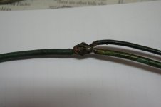
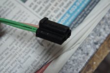
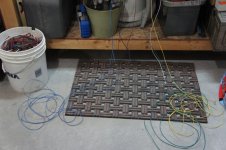
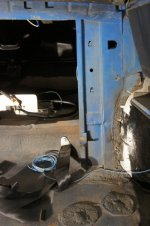
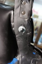
Here's an excellent example of three wires soldered together....somewhat.
This is the high beam wiring that was under the carpet coming from the dimmer switch.
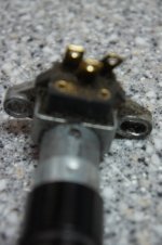
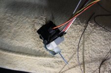
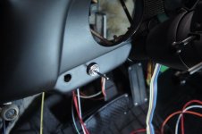
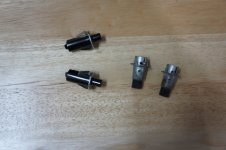
The switch connections were not in a clean condition either, henceforth new dimmer switch being installed..
Click to enlarge photo
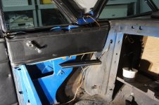
Here's an excellent example of three wires soldered together....somewhat.
This is the high beam wiring that was under the carpet coming from the dimmer switch.
The switch connections were not in a clean condition either, henceforth new dimmer switch being installed..
Click to enlarge photo