|
Brake lines
|
|
|
Text
and photos by Bob Klowak
|
|
|
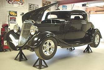
Well
here we are. It's time for the brakes and lines. It would be great to
have a hoist but due to the 9ft clearance of the ceiling we are stuck
with jack stands. Getting your project high as you can helps. What we
are using is a Corvette master cylinder with a 7" diameter power
booster, stainless lines, residual valves, stainless frame through's
,stainless flex lines and a rubber rear flex line. |
 |
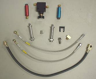 |
Now these are some of the goodies needed to get your brakes to work properly. Depending if you are using disc brakes all round or drums or a combination or the two. Because we are using discs up front and drums in the rear we need some special parts. The blue residual valve is will hold 2lbs of pressure in your calipers. The red holds 10lbs in your drum wheel cylinders. The reason for this is the master cylinder is level and sometimes lower than the two . A siphoning action can occur and you can have no brakes until you pump them. Not good. The black box is a proportioning valve that controls the amount of fluid to the front/rear, to help balance the braking action. |
|
The two stainless tubes with nuts on them are frame feed through tubes. Using these eliminates the practice of putting the brake lines under or over the frame. This is not a good idea to do because jacking the car on your lines is taboo to say the least. |
 |
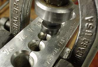 |
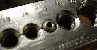
Flaring a line is very simple. The brake line must protrude from the tube clamp by the height of the first step of the flair nipple. The matching nipple is then put inside the tube and then the flare tool is placed behind it and tightened. We used stainless tube and it is harder than regular anodized steel tubing so a lot of pressure is used. When doing stainless you might put the tube clamp in the vise for added pressure to keep the brake line from sliding. Make sure you use the side of the tube clamp that is tapered and the tube sizes are shown. |
|
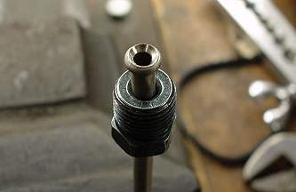
After releasing the flair tool and removing the nipple the first stage of the process should look like this. So far so good. |
 |
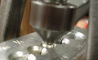 |
Now take the flaring tool and wind it down into the bullet shaped end of the tube and until you feel it get tight. |
| You should end up with something that looks like this. This angle is 45 degrees and will match up to pretty well everything out there. Oh yes, don't forget to put the nut you are using on the tube before you start. If you do forget and it's the first flair you can slide it on from the other end. Carefully bend the pipe the shape you desire by hand or a neat job is done with a tube bender. Always route the tubes in areas that are less to damage and never under or over a frame. |
 |
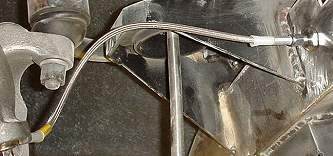 |
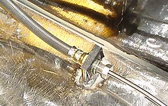
These stainless flexible lines are then connected from the feed through tubes to the calipers in the front, keeping in mind to arch them to clear moving parts or rubbing areas . Try moving the steering back and forth and bouncing up and down. You don't want the hose rubbing. |
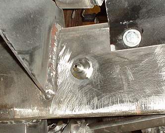
| When you come to a flex line a small plate must be welded to the frame. The flex hose is then put through a hole made in the plate and a clip is installed to secure the hose. Your brake line is then screwed into the hose end at the plate. |
 |
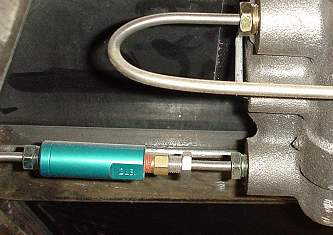 |
As you can see, the blue 2lb residual valve is put in the front brake line. This must be installed between the master cylinder and where the line splits into two lines. One for the left caliper and one for the right caliper. The residual valves are also marked with an arrow to go in the direction of the calipers. |
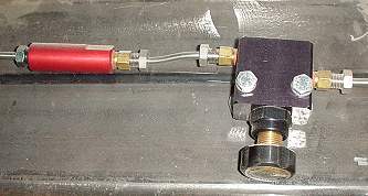
| This
view is of the rear residual valve and the adjustable proportioning valve.
Later when the car is reassembled after its disassembly to finalize the
frame welds and painting of the frame, we will then fill the master cylinder
and go through the bleeding process. There is a neat drawing of the brake
system on the Canadian rodder '32 build-up. This will give you an idea
of the general configuration. brake system diagram |
 |
|
|
|
|
Copyright
© 2001-2003
canadianrodder.com/eFX Design
|
|