| |
Brake
lines and sway bar to finish up the chassis
by Frank Colgoni |
| |
|
|
|
Brake
Lines
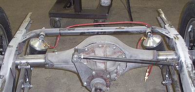
The photo below shows the rear of our frame prior to the installation
of the brake lines and sway bar. We opted for stainless lines
which come in kit form from Horton Street Rod Products. The lines
come bundled with stainless braided flex hoses, thru-frame fittings,
bulkhead fittings, aircraft-style fittings and aluminum line clamps.
Horton recommends a good tube bender like a Godman for the stainless
lines. There's a premium for stainless so you want a nice, neat
job.
|
| |
|
| |
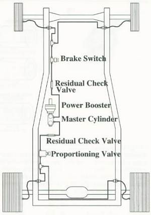
This
illustration, courtesy of Horton, shows the layout of our installation.
Our brake system begins with a vacuum assisted Corvette-style master
cylinder (with equal sized primary and secondary reservoirs) and
finishes with Wilwood disks at all four corners. As such, 2 lb.
residual check valves are used (10 lb. if using drums). The only
variation in our system from the illustration is that we are opting
for a Ron Francis Wire Works mechanical brake light switch versus
an inline hydraulic switch.
Note: In front disk /rear drum setups, the larger reservoir of the
master cylinder (when reservoirs are not the same size) should feed
the disks. |
| |
|
| |
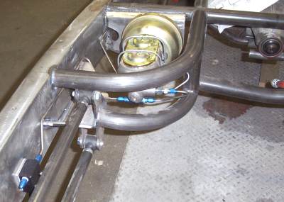 Our master and vacuum booster. The rear check valve is just below
the master.
Our master and vacuum booster. The rear check valve is just below
the master.
The proportioning valve can be seen in the lower left. |
| |

Proportioning valve
|
| |
 Just
in front of the rearend where the circuit branches
Just
in front of the rearend where the circuit branches
to feed the passenger side rear. |
| |
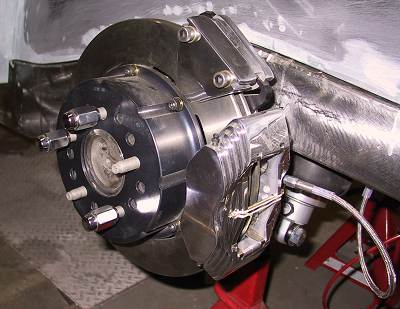
 Drivers
side flex line terminating at the caliper.
Drivers
side flex line terminating at the caliper.
You can see that the end of our frame rail has been closed
for neat appearance where the rear frame horn section begins. |
| |
 Up
front showing the drivers side feed and branch to passenger side
Up
front showing the drivers side feed and branch to passenger side
utilizing the front crossmember. |
| |
 Another
shot of the master tucked into the
Another
shot of the master tucked into the
frame centre section. |
| |
 Flex
hose terminating at the passenger side rear caliper.
Flex
hose terminating at the passenger side rear caliper. |
| |
Rear
Swar Bar
We've selected a Horton sway bar kit which, unlike some kits on the
market, encloses the bar in a tube. The finished appearance is nicer.
The bar itself is 3/4" in diameter. Normally, the carrier tube
would attach to the coilover bolt. Because of the Air Ride Shockwave
units, ours mounts inboard of the shock bolts. |
| |
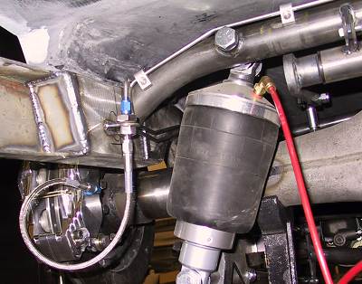
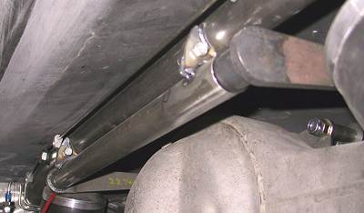
 In this photo, you can
see the sway bar carrier tube mounted just
In this photo, you can
see the sway bar carrier tube mounted just
below the crossmember. The arms face the front of the car and
attach to the rearend with brackets and links with rod ends. |
| |
A shot looking across
the sway bar assembly from the passenger side.
|
| |
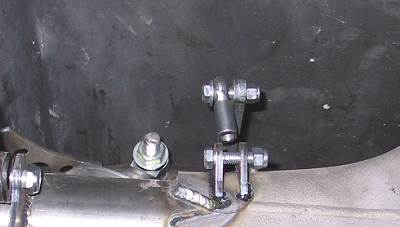 This photo was taken from
the front side of the rearend.
This photo was taken from
the front side of the rearend.
In the centre of the photo at top is the end of the forward facing
sway bay arm. A rod end is threaded into the connector which
is then connected to the small bracket welded to the rearend housing.
|
| |
|