
Navigation
Install the app
How to install the app on iOS
Follow along with the video below to see how to install our site as a web app on your home screen.

Note: This feature currently requires accessing the site using the built-in Safari browser.
More options
You are using an out of date browser. It may not display this or other websites correctly.
You should upgrade or use an alternative browser.
You should upgrade or use an alternative browser.
Home built tools & machines
- Thread starter unclebill
- Start date
unclebill
Active Member
Ok bct, I'll take a chance on this. Could this be a propane forge and the top beside it ? Your slapsticks? for bodywork look sharp. I am trying to figure how to build a sheet metal break for bending 48" wide tin for my floor boards. I thought I had it all worked out but I need to see one in person again. Thanks for sharing BCT. UB
bullet
Well-Known Member
I've never made any big or elaborate machinery, but I have made small things to get a job done.
I made a coil spring compressor once so I could install the coils in a Mustang front end, that was not the safest tool I've ever seen. Down right dangerous when I think about it.
I made a coil spring compressor once so I could install the coils in a Mustang front end, that was not the safest tool I've ever seen. Down right dangerous when I think about it.
How about modifications to tools?
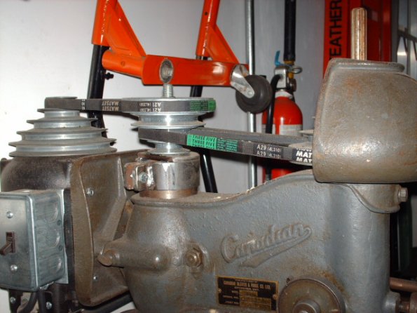
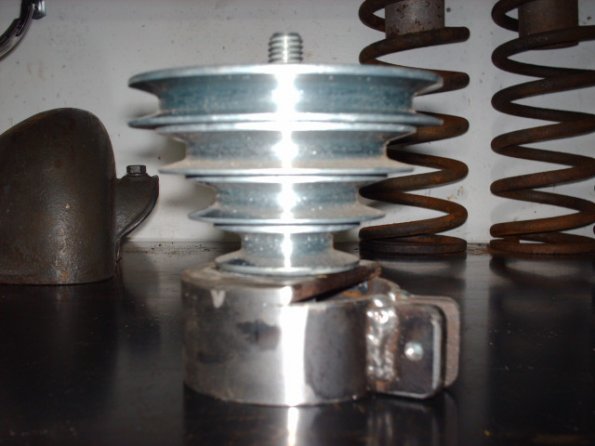
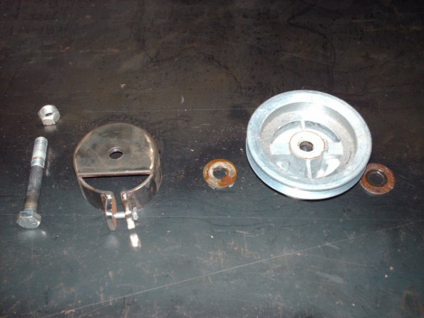
I made this slo-speed adapter for my drill press out of scrap metal and a pulley. Been using it for a couple of years now, great little attachment.
Its probably a good thing that I have no more room in the garage, or else I would be building half the things I see in here!
I made this slo-speed adapter for my drill press out of scrap metal and a pulley. Been using it for a couple of years now, great little attachment.
Its probably a good thing that I have no more room in the garage, or else I would be building half the things I see in here!
unclebill
Active Member
That works for me, this is the type of things I had in mind, Wether you make your own tools or modify them for your own purpose, it all counts. I would rather fix or modify old tools than toss them in the dump. Most of the stuff nowadays is just crap. I have an old wood band saw that I was thinking of using an pully setup like this to slow it down so I can cut aluminum. UB
bct
Well-Known Member
aluminum cuts nice at normal woodworking speeds with a little wax,
nice work keeper ,
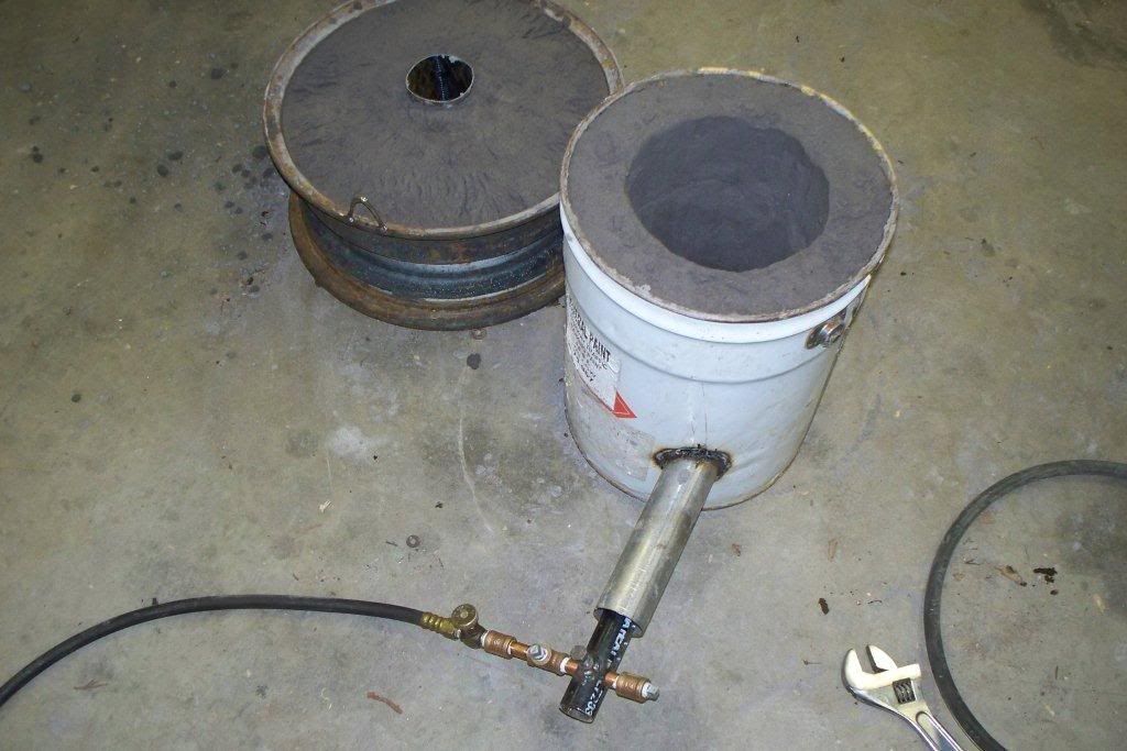
you are right unclebill, thats a furnace/forge i'm going to cast some aluminum .....some pelton wheel paddles first , then some hot rod stuff.....copied pretty much 100% from loudpedal's tech post on the other site.....mixed my own sand as well, from locally obtained materials. only two small explosions....")
nice work keeper ,
you are right unclebill, thats a furnace/forge i'm going to cast some aluminum .....some pelton wheel paddles first , then some hot rod stuff.....copied pretty much 100% from loudpedal's tech post on the other site.....mixed my own sand as well, from locally obtained materials. only two small explosions....
liquidsteel
Member

This is a 3 in 1 machine, It is a english wheel, air planishing hammer and a pullmax machine. It has a 48" throught, stands about 7 feet tall and is full of about 300lbs of sand, all 3 attachments bolt off the top of the frame, the lower adjuster is a foot hydrolic pedal, all the dies for the planishing hammer and pullmax are made from 304 H stainless( which is a hardened version of regular 304 stainless) which I machined from 2" by " square stock, the wheel dies I got online in a 10 piece kit. I was bored 1 day and painted it silver, blue outline and topped it off with HOK kamin blue mini flake
Not sure what the thumbnail die does, other than a tool used by the Japanese to torture POW's in WW2
Hey Bullet,
Can be used to create tucks in a metal sheet ... shrinking its perimeter and bringing the centre up when fabricating such things as the sides of a motorcycle tank or fender.
wow all good Ideas bct gave me a site so's I could build a small furnace for melting aluminum it worked great and I like making my own tools as well but some times buying is faster and safer like bullit did made my own spring compressor it worked well but used the peices in some thing else after the job was done!!
Hi guys!
Here's my wheel. 32" throat, upper adjuster. Classic shape...2 C's fabricated from 1/2" plate with a 4"x3/8"tk spacer rolled around the perimeter.

The 1/2" steel plate C's were ordered from the local steel supplier who laser cut them to the provided CAD drawings. Since my Millermatic 210 is only rated for 3/8" material, I decided to have the frame welded up at a local fab shop. This is what it looked like when it arrived.
Also, on the left there, you can just make out our tipping wheel mounted to the bench.

The base was fabricated using some material I found around the shop. Also, aligning the upper and lower box tubing for the anvil holders at this stage to ensure they run true to each other. The excess material will be trimmed off.


The decision was made to mount the anvil holder on the side that I'll be using the wheel the most. I've seen some placed on the back, but if the unit is backed up against the wall as in my case ... I feel it'll make it more of a challenge to get to them.
Here's my wheel. 32" throat, upper adjuster. Classic shape...2 C's fabricated from 1/2" plate with a 4"x3/8"tk spacer rolled around the perimeter.
The 1/2" steel plate C's were ordered from the local steel supplier who laser cut them to the provided CAD drawings. Since my Millermatic 210 is only rated for 3/8" material, I decided to have the frame welded up at a local fab shop. This is what it looked like when it arrived.
Also, on the left there, you can just make out our tipping wheel mounted to the bench.
The base was fabricated using some material I found around the shop. Also, aligning the upper and lower box tubing for the anvil holders at this stage to ensure they run true to each other. The excess material will be trimmed off.
The decision was made to mount the anvil holder on the side that I'll be using the wheel the most. I've seen some placed on the back, but if the unit is backed up against the wall as in my case ... I feel it'll make it more of a challenge to get to them.
Oooh, nice bit of work,
Nick, when you're done with that, you can send it my way. Prepaid please.
Ha! Funny
I think the courier would have a devil of a time lifting it. It's really enjoyable to use...so I don't think I'll be parting with this one any time soon...sorry.Now onto something a little more serious
... please don't laugh at the next photo.Here's the predecessor to the orange wheel...built it before I knew what an english wheel was...to save my arm from all the planishing that had to be done on my project...

In an effort to speed up the metal shaping process I was wondering if two steel wheels, one with a crown(bottom)...the other flat(top), would produce the same result as me stretching the metal by hitting the hammer against the dollie in a longitudinal direction. After scrounging some bearings, box tubing, and utilizing the adjuster on our press I came up with this crazy machine.
And while there were some serious drawbacks like the height between the anvil mount arms, and the extremely narrow point of contact ...it worked! Yes, there was some tracking in the pieces...but most of it was smoothed out running perpendicular with really light pressure...and the remainder with the good ol' hammer and dollie.
Last edited:


With the latest discussions on metal shaping thought I'd revive this thread with a new slapper I created last weekend. As R2's body is coming closer to completion and I'm preparing to start mating panels to each other I decided to create a new .. smaller slapper ... to massage the panels.
Doesn't take long to fabricate one...bout 25 minutes...and you can create a surface profile that meets your requirements. Usually, flatter is better...but not too flat. Spreads the impact's contact face over a larger area resulting in averaging out convolutions in the metal.
Rough outline of the overall general shape on truck's leaf spring.

Starting to cut out the slapper.

Ready to start shaping the profile.

Using 'The Wolf' to create the face profile.

We don't encourage the use of grinders with the guards removed....


Final shaping completed with a file and 300 grit sand paper.

Done! Handle offset bent to the 'correct' feel with the O/A torch.

Doesn't take long to fabricate one...bout 25 minutes...and you can create a surface profile that meets your requirements. Usually, flatter is better...but not too flat. Spreads the impact's contact face over a larger area resulting in averaging out convolutions in the metal.
Rough outline of the overall general shape on truck's leaf spring.
Starting to cut out the slapper.
Ready to start shaping the profile.
Using 'The Wolf' to create the face profile.
We don't encourage the use of grinders with the guards removed....
Final shaping completed with a file and 300 grit sand paper.
Done! Handle offset bent to the 'correct' feel with the O/A torch.
Last edited: