1956 Chevy Pickup Project

Update...

This might be the last update for a while, since we will be heading south this week, but I wanted to show what had been done to the frame since it left the shop.
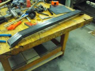
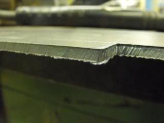
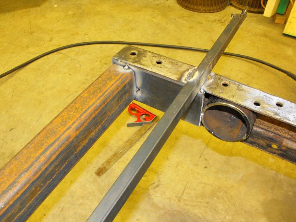
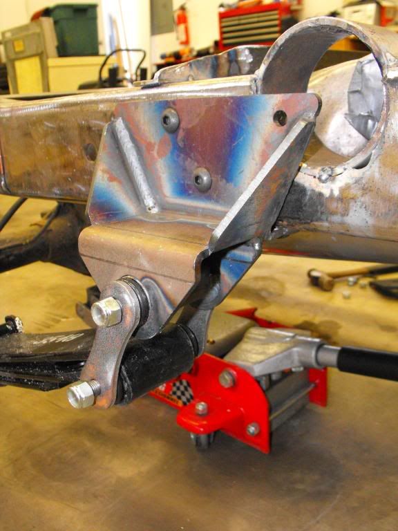
We got it home and I set it on jack stands. I started at the back, building a cross-member out of 2”x3” 3/16ths wall tubing for a rear cross member that I can weld a hitch to, in case I end up towing something with the truck in the future. This required a pair of boxing plates. Nothing new or earth shattering here.

rearboxingplate2.jpg


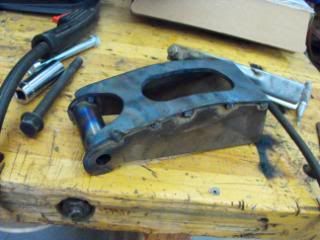
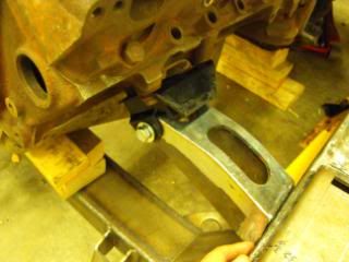
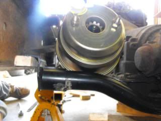
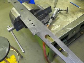
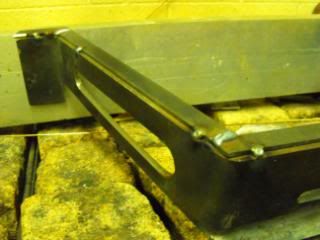
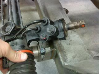
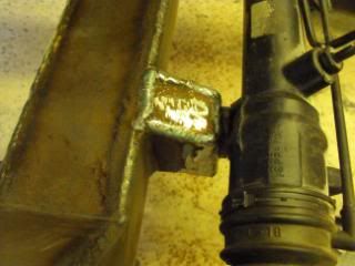
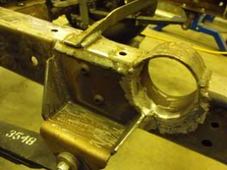
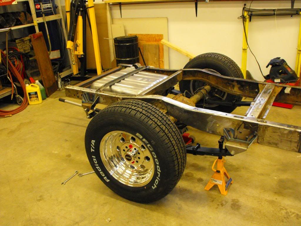
I then moved on to fabbing up brackets and straps for the gas tank that is going behind the diff under the bed. I hate the notion of filling up a truck by dragging the hose over the box sides and inserting the nozzle into the center of the bed. Just ain't right, if you ask me. I decided upon a tank for a '57 chev car, since the pickup and filler neck locations are suited for what I have in mind. I will be putting the filler neck somewhere outside the box. This required modifying the frame to allow the filler hose to pass through. I tacketd a piece of 3 1/2” 3/16ths round tubing to the frame to facilitate this.

fillerneckhole2.jpg


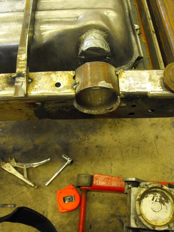
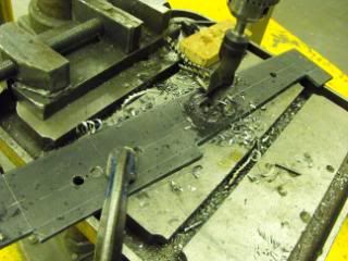
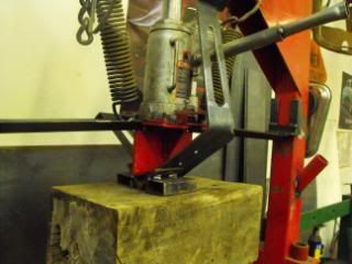
The cross member in front of the tank also required a notch to provide room for the fuel lines and fuel pickup. The tank straps were bent out of 1 1/2” x 1/8 mild steel and shaped to fit the tank profile closely. Now the looks like it was meant to be there all along!

gastank2.jpg


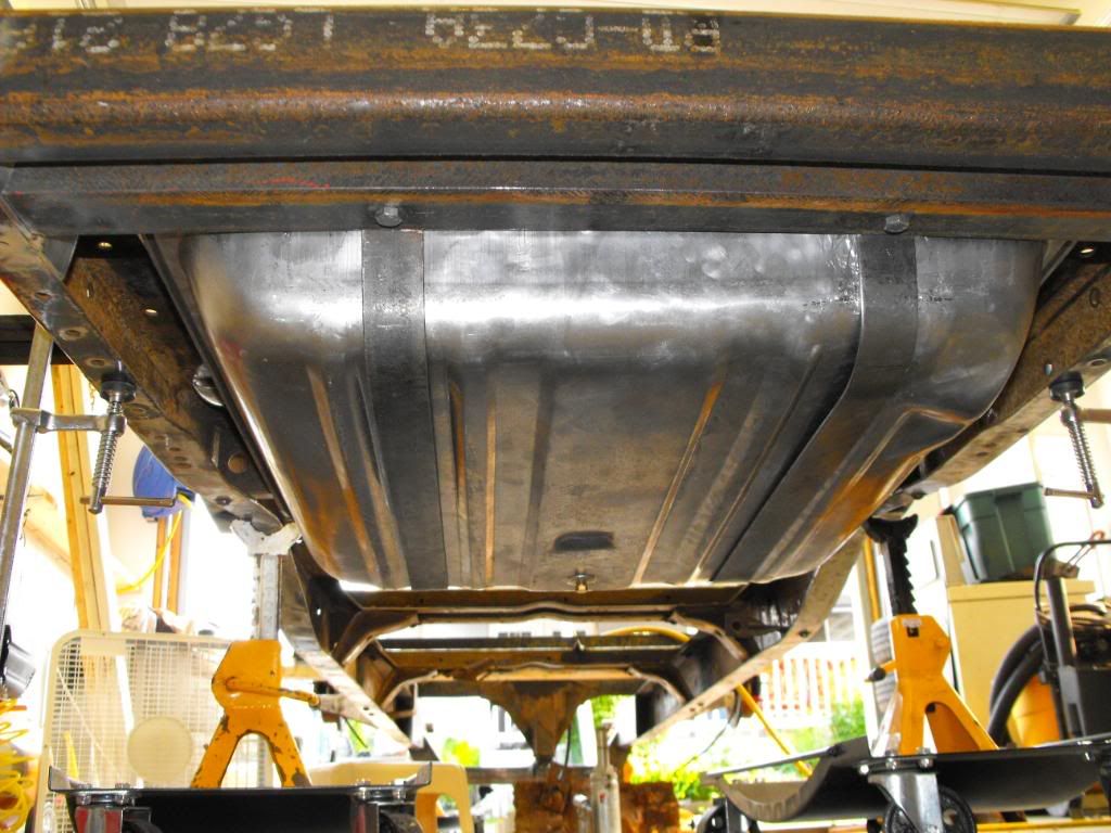
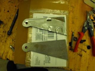
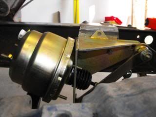
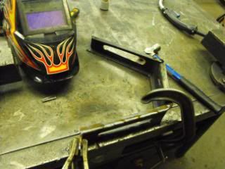
Shortly thereafter, I bolted on the TCI rear spring kit. I was impressed with the quility of both the welds and the bends in the 3/16ths stock. Everything had nylocs and fine threads. The allen head bolts are a bit of a pain - I had to go out and specifically buy a socket to torque them up, but they do look nice. Had a few holes to drill, but everything went together without any issues, but one. The only problem I encountered was the location of the filler hole that went through the frame – turns out it was right at the edge of the rear spring bracket. Even though the kit is designed to be bolted together, I will be welding that particular brakcet on and trimming it to fit around the filler hose hole. This will have to wait until we get back from our trip.

Rearspringbracketintheway.jpg


So this is pretty much how she sits for now. I did mock up the frame with the new wheels I am putting on her - she is starting to look like something now. Mmmmm - I love shiny!

Wheelymockedup.jpg

After I shot this last photo, I did put the cab on so that when we get back from Mexico I can set upt he engine and trans mounts. Cheers.
 
Good progress W-Butcher! I'll see if I can sneak over before you're deported and have a lookie-loo.
 
from the picture.... it looks like the filler may be located behind the wheel... gas door behind the fender on the step side?? or now that I've said it... a hidden filler undernieth the rear step on the step side would be trick too... I've never seen that I dont think
 
Back in the saddle, but still working on the frame.

1949
Well, it has been quite a while and I think I am way behind in my build thread so it's time for another update.

I think I need to put in some type of disclaimer at this point. My humble intent with this thread is just to document my build and share it with whomever gives a crap. I'm sure there are many other ways of going about this build and that some of you in cyberspace are shaking your head. In no way is it to portray myself up as some kind of guru or hotrod god! Please understand that much of the work done here is trial and error and also with the help of invaluable friends. So now, on with the show...

The frame still needed a few more things before I can paint it – like motor and trans mounts. I spent lots of time mocking up the engine and trans with the distributor, water pump, oil pan, dipstick tube and valve covers in place, making sure the drivetrain was centered and I had exhaust, radiator and firewall clearance and the correct drivetrain angle (thanks for those who offered suggestions when I got stuck!) Originally I was thinking that I would just use the pair of aftermarket motor mounts that came with the truck, but after eyeballing them for a while I decided that I just didn't like them - they were too butt ugly. Time to come up with something better, since motor mounts are very visible and I figured they needed to look decent. After looking online, I decided to use a couple of brackets from Hortons Welder Series – good raw material to start with.

MotorMounts1Template.jpg
MotorMounts2.jpg
MotorMounts7.jpg


I didn't want my mounts to look like big blocks of industrial sized steel, so I changed the lines and added a sweet little curve, The top plate needed a little pazazz as well, so a fish mouth at one end and an oval on the top was included in the design just for giggles. (I now sense a theme coming for anything else I fab up.) I heated the top plate with the oxy to form it around the curve of the side plates, then tacked it into place. The tubular spacer was turned on the lathe and the rubber clam-shell style motor mount fits nicely over it all. I welded it up at work and then tacked the mounts onto the frame. Sweet! Now I won't have to drive around with blocks of wood holding the engine in place!

I then moved on the trans mount. Again, the truck came with an aftermarket tubular cross-member and trans mount that I thought could look respectable since it looked decent enough. I spent several hours of diddling and fiddling under the frame getting the trans where I needed it and mocked it all up. Once set in place, I installed the brake booster bracket for the under cab brakes to the frame – that's where things started going wrong. Whomever designed the cross-member did not consider a power brake booster being used under the floor of the cab in the stock location – no way would it even come close to fitting, no matter how big a hammer you had.

Aftermarketx-memissue.jpg
Aftermarkettransx-mem1.jpg
TransX-mem1notchedandbent.jpg


The aftermarket member was put aside and after some thought I picked up a piece of 1x2 rectangular tubing to use as a cross member. At this point I tacked in some boxing plates as well. I originally considered mounting the the 1”x2” cross member that I was going to fab up to mount to the top of the frame, but after some more thought and input from a buddy I decided to box the frame, cut a couple of wedges out of the member and weld it to the boxing plates. The trans bracket simply bolts to the underside of the cross-member. I drilled the holes in the member and made up a pair of 1” diameter threaded inserts to bolt the member to, so the 1x2 doesn't deflect when things are tightened down.
 
Last edited:
I still needed a bracket to drop down to the trans, so I mocked one up out of cardboard. I had an odd shaped piece of 3/16ths plate that would work, so I laid out the design and cut it out with the plasma cutter. Wow! What a nice job it did of the edges! Hardly needed touching up with the grinder! I then drilled holes for the transmission bolts and added a couple of slots on the bracket for aesthetics again to keep with the theme started with the motor mounts. The zip cut made quick work of the slots. Oxy was used to heat the plate and put a gentle curve in the leading edge of the bracket to strengthen it up. The next day I was off to Tinn's place to use his press to bend the bracket into shape. A bend here, a fold there and things were starting to look pretty good.

Transbracket4edges.jpg
Transbracket5drilling.jpg
Transbracket7zipcutting.jpg


Transbracket9bending.jpg
Transbracket14tacked.jpg
Transbracket18welded.jpg


While in bed that night I considered the transmission bracket and concluded that there could be too much flexing with a piece of flat bar when under load. So the next day I took some 1/2” x 1/8" flat stockbar and added some reinforcement along the edges. A few welds and a few more bolt holes later and the job is completed. I'm pleased with the results as it is both aesthetically pleaseing and more than strong enough, without being overkill. With everything centered and all measurements double checked it was all tacked together. I am just going to leave it tacked for now until it's all finished and I am happy with it all before doing my final welding.
 
Last edited:
W/B are you and your skop on the garage tour this winter? I'd really like to have a look. I think it's a very impressive build. And with 2 49s sitting in the yard- who knows.
 
Thanks for the post, I have that very frame jig in my garage right now with my '30 Hudson chassis on it. You guys pieced together a good jig, Thanks...
 
W/B are you and your skop on the garage tour this winter? I'd really like to have a look. I think it's a very impressive build. And with 2 49s sitting in the yard- who knows.

Hadn't really thought about it. shop is pretty small, 20x25 - besides you pretty much seen it all here. I f you want to come by for a visit some time to shoot the bull, PM me.
 
lookin amazing there Gavyn. Im too impatient to do it all at once as you are, but i really admire the workmanship!!
 
2706
Now that the truck is back at home I am working solo for the most part. Tinn comes by occasionally and Leadfoot (Bob) and I hang out often, so I get plenty of input. I had a lot of interruptions over the last while with some bathroom renovations and the house needing attention, but have been able to get back at it lately.

I turned my attention to the steering on my truck. The truck came with a new Mustang II rack, a heim-end type support and 18” of double D shaft as part of the cross-member kit. I wanted to use what came with the truck as much as possible, so as to reduce my expenses on the build. I dug up a GM tilt column from a parts car that Bob had and mocked it into position with bungee cords. When it came time to bolt the rack into place I noticed that the input shaft on the rack was almost horizontal. This would require an intermediate shaft with 3 universal joints. I wasn't too happy with this and started looking around at other options. To improve the angle, I modified the rack mounting bosses on the TCI cross-member, by cutting the boss, prying it open to make the mounting surface vertical and welding in a wedge of steel to fill the gap. While at it I enclosed the top of the boss to add a little strength. Now the input shaft is pointing almost directly at the column – much better. I did end up removing the spacers that came with the kit to keep things in proper alignment.
MustangRackMountmodification2-1.jpg
DSCF0023.jpg
DSCF0029.jpg


I tossed around the idea of using the DD shaft, but two things are holding me back... the cost of the borgeson joints and the look of it. Bob lives a couple of blocks away and so I went to see his build (a GM A-body clip mated to his 57 truck). He had the advantage of using all GM stuff and had a pretty direct shot from column to steering box, so he could use an S10 intermediate shaft. With a rag joint at one end and universal at the other, that just wouldn't work with my situation. He suggested a shaft out of an astrovan/

Sounds like time for a hunting trip, so off to the wreckers I went with my 16 year old daughter, Terry. As a new driver, she is trying to get as much seat time as she can, even if it means going to the wreckers and trudging through the mud with dad. An hour and $20 later we came away victorious. I horrified Terry as we were leaving by telling her the guys at the yard were extra generous with tools and help because she was there, haha. I should bring her along more often!

Back at home I tested the shaft: matches the column perfectly, but as I suspected, no dice at the Ford end. It makes sense when you think about it: generally Ford parts do not interchange with themselves (think 351's), so what are the chances it'd work with the GM shaft?? It would've been too good to be true. Anyways, the rack's input shaft size matches the intermediate shaft's universal female end (3/4”), but it has a 36 spline count while the GM shaft spline count is 30. I really want to keep the astrovan intermediate shaft – it's a neat piece, it even collapses from 21” down to 15” - and it is pretty small to give me clearance around the header, as well as a universal at each end. But now I need to find another solution. Asking questions on this, and other, forums have yet to yield the ultimate solution. The closest solution so far came from Johnny37 at Old Car Center – borgeson makes a coupler with 3/4” - 36 spline female at one end and 3/4” smooth female at the other end. This might be able to be pinned to a cut section of input shaft from the astrovan box. Unfortunately, after a second trip to the BCR I found that the input shaft is too short. Oh, well, it isn't going to be as easy as I'd hoped. Does anyone know if there is a collapsible Ford intermediate shaft out there with 3/4”-36 spline and a 1”DD hollow shaft? I may be able to mate the two together.
DSCF0057.jpg
DSCF0115.jpg
DSCF0118-1.jpg


So while I research and chew on that problem I continued working on other parts of the chassis. I boxed the front end of the frame with some 3/16” plate and built a cross-member out of some 2x3. Couldn't leave it alone and drilled a few holes, etc. so it matched the motor mounts and trans mount. I recently bought a new welder, stepping up to a 230v Lincoln (got a smoking deal at Canadian Tire of all places), and bought a new Miller welding helmet to replace the Princess Auto helmet I had. It’s amazing how a person’s welds improve when they can see! This gave me the excuse I needed to try it out, so I welded the cross-member right under the mounting brackets of the rad support. I dunno if in the long run it can even be seen, but I know its there and think it suits the build so far. I also took some time to finish some other welding and finished off the mounting of the rear spring perches, in particular, the drivers side (it had to be trimmed and reinforced). That's about it for this installment.