
Navigation
Install the app
How to install the app on iOS
Follow along with the video below to see how to install our site as a web app on your home screen.

Note: This feature currently requires accessing the site using the built-in Safari browser.
More options
You are using an out of date browser. It may not display this or other websites correctly.
You should upgrade or use an alternative browser.
You should upgrade or use an alternative browser.
1946 Oldsmobile sedanette
- Thread starter MGTSTUMPY
- Start date
MGTSTUMPY
Active Member
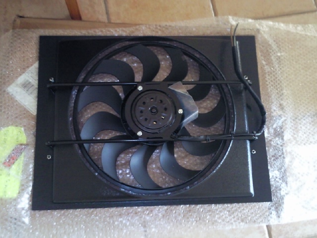
Rather than buy a local radiator from a known supplier and given mine and everyone else's experience with them, I decided to err on the side of caution, spend the extra and purchase a quality Walker product with AC condensor, shroud and electric fan. Rusty Olds (Gary) was over in US the other year for work so I had it sent to his friend's house in Kansas. He was kind enough to bring it back with him to which I'm eternally grateful. It saved on freight ($$$$) and was a LOT cheaper than buying it locally. It should be a bolt-in according to Walker.


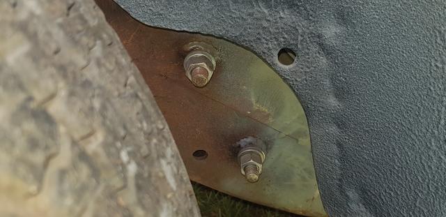
These are the seat belt mountings I mentioned. Plug welded through outer panel and fully at boss. I was able to slide the flat plate up the 'B' pillar and then drive it home before welding in place


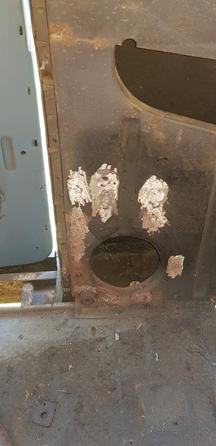
These are the seat belt mountings I mentioned. Plug welded through outer panel and fully at boss. I was able to slide the flat plate up the 'B' pillar and then drive it home before welding in place
Last edited:
MGTSTUMPY
Active Member
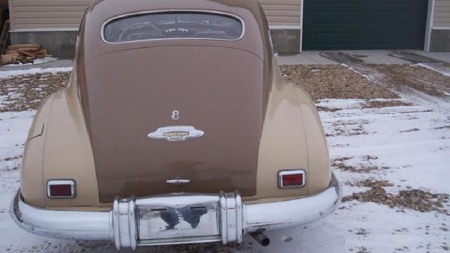
Since my Olds is a model 76 ( 6 cylinder) I picked up a trunk emblem '8' off a model 78 (8 cylinder) that I've yet to attach.


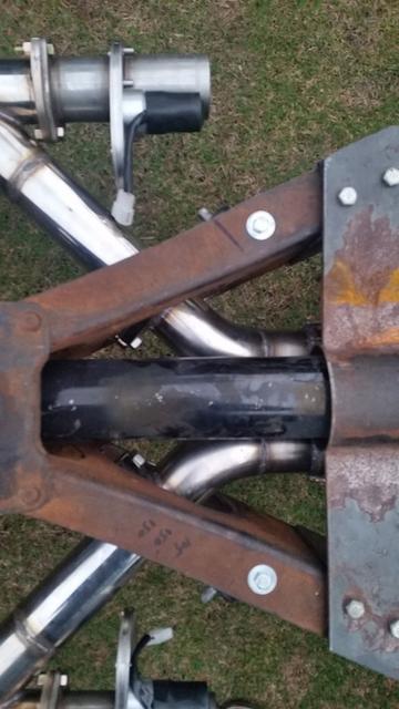
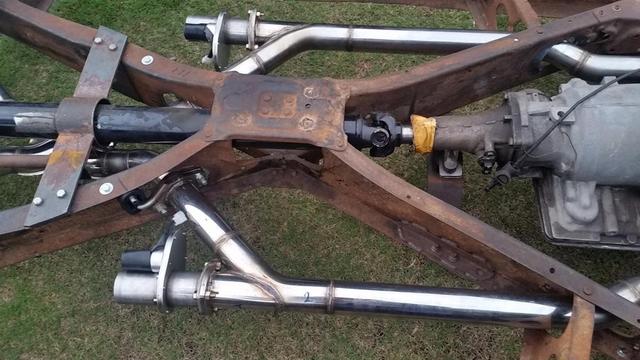
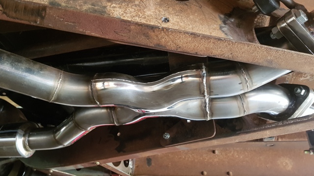
I only have the last 1m of exhaust to do and the system is complete. I replicated the OEM belled hole for the exhaust on the other side of the centre x-member to maintain that OEM appearance and added 2 x more behind rear centre x-member to keep everything up close and off the ground. Only 1 hole for inline 6 & 8 cylinders as V8's didn't come out until 1949. OEM style flange rolls from one side to the other, allowing more exhaust (2 1/2" diameter) clearance. Pipes go through holes and into X-pipe directly below driveshaft and, forward torque rod / driveshaft safety loop. I put some turn downs on each pipe behind the Dougs Headers electric cutouts.


I only have the last 1m of exhaust to do and the system is complete. I replicated the OEM belled hole for the exhaust on the other side of the centre x-member to maintain that OEM appearance and added 2 x more behind rear centre x-member to keep everything up close and off the ground. Only 1 hole for inline 6 & 8 cylinders as V8's didn't come out until 1949. OEM style flange rolls from one side to the other, allowing more exhaust (2 1/2" diameter) clearance. Pipes go through holes and into X-pipe directly below driveshaft and, forward torque rod / driveshaft safety loop. I put some turn downs on each pipe behind the Dougs Headers electric cutouts.
Last edited:
MGTSTUMPY
Active Member
Here's a photo of X-pipe between frame rails. Everything is compact and serviceable and mounted high for clearance.
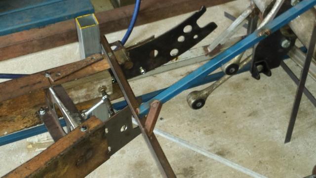
Sway bar brackets, F&R, are next on the agenda. I'm doing away with OEM links and using SS rose joints with poly bushings. I require room at the front for Shockwaves and will turn the rear bar around 180 degrees (Forward mounted and pivoted off new dog bone bracket) due to gas tank being where the trunk floor is on C4s. This is a '57 Chevy with C4 IRS and forward mounted sway bar. All I need to do is set correct geometry and fabricate frame brackets.


This is another Olds 78, same OEM colours as my car will be when finished, note '8' emblem is mounted above trunk emblem, I think I like it better below the emblem. As a side note, I modified the OEM rear over-riders and mounted NOS front park lamp assemblies in them for reverse lamps and traffic indicators. I have a NOS Guide B31 backup lamp however I don't want to cut anything to use it. I might replicate another OEM GM bracket and mount it off to side of rear over-rider. It attaches via a bumper bracket and bolt.

Sway bar brackets, F&R, are next on the agenda. I'm doing away with OEM links and using SS rose joints with poly bushings. I require room at the front for Shockwaves and will turn the rear bar around 180 degrees (Forward mounted and pivoted off new dog bone bracket) due to gas tank being where the trunk floor is on C4s. This is a '57 Chevy with C4 IRS and forward mounted sway bar. All I need to do is set correct geometry and fabricate frame brackets.
This is another Olds 78, same OEM colours as my car will be when finished, note '8' emblem is mounted above trunk emblem, I think I like it better below the emblem. As a side note, I modified the OEM rear over-riders and mounted NOS front park lamp assemblies in them for reverse lamps and traffic indicators. I have a NOS Guide B31 backup lamp however I don't want to cut anything to use it. I might replicate another OEM GM bracket and mount it off to side of rear over-rider. It attaches via a bumper bracket and bolt.
Last edited:
I’m sure that radiator would fit mine, I wonder if you would miss it.
MGTSTUMPY
Active Member
I could use the F&R C4 composite mono leafs however I'm using Shockwaves on all corners with a self levelling kit. Legislation here requires 125mm ground clearance on my Olds due to 125" wheelbase. I set the frame up at ride height taking into consideration body overhang and allowing 125mm ground clearance to bottom or rockers.
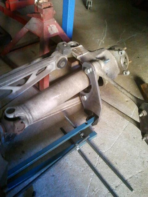
I then levelled the frame and set up IRS & IFS at ride height. Jigs and threaded rods with washers/ jamb nuts held everything in place once frame and suspension components were levelled and moved into correct place. A lot easier then to make cardboard templates and have brackets etc laser cut for perfect fit. A giant jigsaw that was tack welded together.
The IRS was set up with rear driveshafts and top dog bones parallel to ground, prevents brinelling to the bearings; lower front control arms were also set up parallel to ground with F&R setups mimicking OEM GM geometry. Damn, a lot more work this time around compared to when I installed the IRS (Jag) and IFS (GM) in my 35 Chevy tub 15yrs ago.
Lots of measuring lengths and diagonals, checking heights, clearance and double checking. The trammel bar I made is better than trying to hold a tape measure and get accurate reading over large distance. I made different tips to allow for differing depths and frame holes sizes as well as having the versatility of short and long rods to suit a variety of short, medium and longer lengths. Once welded up it's too late to alter or change later. Measure twice, cut once.
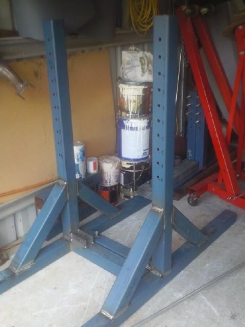
I also built a rotisserie from thick wall RHS and added hydraulic rams. Not a light weight however it's been so handy for turning frame and body around allowing easy access to everything, measuring, cleaning, welding etc.


I then levelled the frame and set up IRS & IFS at ride height. Jigs and threaded rods with washers/ jamb nuts held everything in place once frame and suspension components were levelled and moved into correct place. A lot easier then to make cardboard templates and have brackets etc laser cut for perfect fit. A giant jigsaw that was tack welded together.
The IRS was set up with rear driveshafts and top dog bones parallel to ground, prevents brinelling to the bearings; lower front control arms were also set up parallel to ground with F&R setups mimicking OEM GM geometry. Damn, a lot more work this time around compared to when I installed the IRS (Jag) and IFS (GM) in my 35 Chevy tub 15yrs ago.
Lots of measuring lengths and diagonals, checking heights, clearance and double checking. The trammel bar I made is better than trying to hold a tape measure and get accurate reading over large distance. I made different tips to allow for differing depths and frame holes sizes as well as having the versatility of short and long rods to suit a variety of short, medium and longer lengths. Once welded up it's too late to alter or change later. Measure twice, cut once.
I also built a rotisserie from thick wall RHS and added hydraulic rams. Not a light weight however it's been so handy for turning frame and body around allowing easy access to everything, measuring, cleaning, welding etc.
Last edited:
John in Oz
Well-Known Member
It is a shame that the photos don't do justice to the work you are doing, there has been a lot of thought go in there.
MGTSTUMPY
Active Member
Well onto the IRS installation so bare with me as I go through the process. So many details so I'll not over complicate things.
My 6m x 6m garage is restrictive with the body off and sitting on a dolly in the next bay. I had to work around my bench and tools. Thank goodness I'm organised and maximise every bit of space I have for storage. Higher shelves on each wall and old beds in the apex to hold even more parts, seats and hood. Fender and other sheet metal etc were hung off the walls via hooks.
Anyway once the C4 IFS was installed the frame was a roller again albeit with OEM Olds trailing arm suspension.
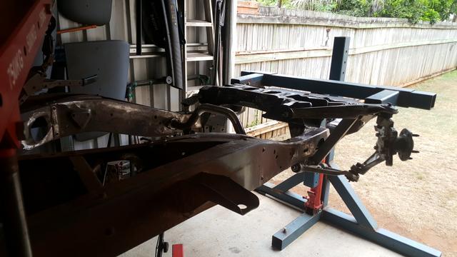
The first thing was to remove the large rear cross-member above the rear axle that held the rear coil springs. You'll note the rear legs of the centre x-member extend into both rear frame rails. I wanted to retain the OEM style legs, box the rear frame rails and reinforce the legs with upper and lower gussets where they would be reattached to the frame rails after I fabricated new end sections which allowed access to forward mounting points for through frame upper and lower dog bone bolts. Furthermore I wanted to add additional frame brackets between rear frame rails and the rear centre X-member legs to add strength and remove any torsional twist that could result from the IRS.
I later used the OEM mounting holes where the trailing arms attached for the tail shaft safety loop and forward mounting point for a removable IRS torque rods (Ladder bar). To complete all I need to weld the gussets on, a lot of strength in triangulation when coupled with top mounted IRS bushing. If I ever need to remove the IRS or drive shaft all I need to do is remove the forward bushed end of torque rod which used roll cage bungs and then drop the drive shaft loop and it's done.
Another trick I used whee I could were threaded rods with jamb nuts and washers either side to hold everything square and in position. Plus it allows for minor adjustment once things were cut, that trammel bar made things so easy when it came to measuring and squaring things up; frame, IRS, IFS, measuring from known points ensured things were done right.


My 6m x 6m garage is restrictive with the body off and sitting on a dolly in the next bay. I had to work around my bench and tools. Thank goodness I'm organised and maximise every bit of space I have for storage. Higher shelves on each wall and old beds in the apex to hold even more parts, seats and hood. Fender and other sheet metal etc were hung off the walls via hooks.
Anyway once the C4 IFS was installed the frame was a roller again albeit with OEM Olds trailing arm suspension.
The first thing was to remove the large rear cross-member above the rear axle that held the rear coil springs. You'll note the rear legs of the centre x-member extend into both rear frame rails. I wanted to retain the OEM style legs, box the rear frame rails and reinforce the legs with upper and lower gussets where they would be reattached to the frame rails after I fabricated new end sections which allowed access to forward mounting points for through frame upper and lower dog bone bolts. Furthermore I wanted to add additional frame brackets between rear frame rails and the rear centre X-member legs to add strength and remove any torsional twist that could result from the IRS.
I later used the OEM mounting holes where the trailing arms attached for the tail shaft safety loop and forward mounting point for a removable IRS torque rods (Ladder bar). To complete all I need to weld the gussets on, a lot of strength in triangulation when coupled with top mounted IRS bushing. If I ever need to remove the IRS or drive shaft all I need to do is remove the forward bushed end of torque rod which used roll cage bungs and then drop the drive shaft loop and it's done.
Another trick I used whee I could were threaded rods with jamb nuts and washers either side to hold everything square and in position. Plus it allows for minor adjustment once things were cut, that trammel bar made things so easy when it came to measuring and squaring things up; frame, IRS, IFS, measuring from known points ensured things were done right.
MGTSTUMPY
Active Member
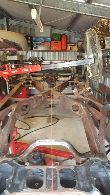
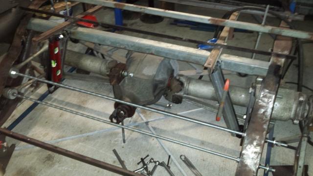
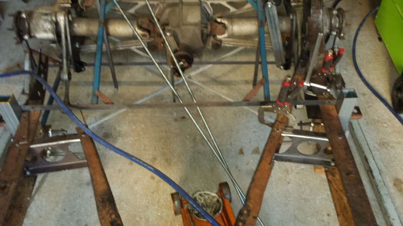
Here goes, after IRS was placed in jig to ensure correct 125" wheelbase was maintained at correct ride height I had to set frame up at correct height and decide how IRS would be attached to frame. Those threaded rods I mentioned earlier came in handy at set up stage, I used them on batwing to get it level, at pinion and at rear of IRS case where monoleaf spring originally attached to housing and setting up rear dog bones to maintain OEM geometry.
Once pinion angle was correct (3 degrees up) with 1/2 shafts and top bog bones level IRS was in position. Time to double check all lengths and diagonals with trammel bar to ensure squareness to frame. I used OEM C4 dog bone mounts to maintain geometry / spacing and determine how things would mount. Some dummy RHS in lieu of OEMs to assist locate things. I started jigging the IRS so it remained where it needs to be position wise, relative to frame. I initially decided to move the rear frame rails inboard (Aka tubbing) however I wasn't comfortable with this decision so I decided to recess the dog bones into the frame. I then filled the OEM spring pocket recesses (Top and bottom) and later flattened the bulge on the outside frame rails for tyre clearance. No big deal really, just another additional and inconvenient adjustment that I needed to make.
Anyway I moved the frame rails back into position after a slight modification


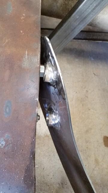
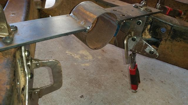
The RHS rear cross member is 5mm wall and is welded to both inside faces of the rear frame rails. Thick plugs were machined up for upper shock mounts and welded in, this is a big heavy car and everything depends on those 5/8" UNF mounting bolts and sturdy cross member supporting the weight.

Once pinion angle was correct (3 degrees up) with 1/2 shafts and top bog bones level IRS was in position. Time to double check all lengths and diagonals with trammel bar to ensure squareness to frame. I used OEM C4 dog bone mounts to maintain geometry / spacing and determine how things would mount. Some dummy RHS in lieu of OEMs to assist locate things. I started jigging the IRS so it remained where it needs to be position wise, relative to frame. I initially decided to move the rear frame rails inboard (Aka tubbing) however I wasn't comfortable with this decision so I decided to recess the dog bones into the frame. I then filled the OEM spring pocket recesses (Top and bottom) and later flattened the bulge on the outside frame rails for tyre clearance. No big deal really, just another additional and inconvenient adjustment that I needed to make.
Anyway I moved the frame rails back into position after a slight modification
The RHS rear cross member is 5mm wall and is welded to both inside faces of the rear frame rails. Thick plugs were machined up for upper shock mounts and welded in, this is a big heavy car and everything depends on those 5/8" UNF mounting bolts and sturdy cross member supporting the weight.
MGTSTUMPY
Active Member
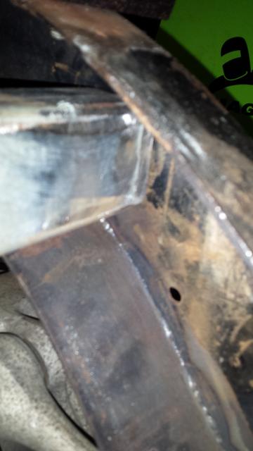
Around this time I also removed both rear legs from the centre cross-member, both required major reconstructive surgery to attach to new boxed rear frame rails. Prior to this I installed these reinforcing brackets I mentioned earlier. Internal fish plates reinforced the entire area where the new legs attached. The legs were modified with flanges top and bottom to better spread the load rather a straight across cut, a lot more strength being staggered. I got a bit ahead of myself as these weren't done until after the dogbone mounts were done and frame rails boxed. I retained the OEM frame flanges and angle cut pipe for bolt access holes. These add strength back and appear OEM. Lots of cardboard templates were used to get shapes correct and mirrored from side to side. Dimples in both rear legs are tapered pipe welded in for fluid lines, no tight corners and plenty of access (Brake, fuel).
This C4 IFS & IRS swap was a steep learning curve Would I do it again, yep, well if someone paid me.


Lots of cardboard templates were used to get shapes correct and mirrored from side to side. Dimples in both rear legs are tapered pipe welded in for fluid lines, no tight corners and plenty of access (Brake, fuel).This C4 IFS & IRS swap was a steep learning curve
Would I do it again, yep, well if someone paid me. MGTSTUMPY
Active Member
After reconsidering how IRS mounted I decided to mount the dog bones bushings in a fabricated frame, so windows were cut top and bottom to facilitate OEM set up at my ride height. The modified frame rails were flattened slightly for an even taper from where it steps up in front of rear wheels to the top where rear shock cross-member connects to frame rails. New inner fish plates were plasma cut and welded into position along with frame rails being welded back into position. Windows were cut into top and bottom frame rails with new sections fabricated to support the top dog bones and sandwiching the bushing OEM (Double sheer) style. Long internal gussets were fabricated to fit snug between top, bottom and inside rail faces to spread the load as well as capturing the bushing in the frame rail pocket. Due to loads in that area, that's why I added those additional rear frame rail gussets to cross member legs and top and bottom reinforcing plates. These strengthen the entire area where rear legs attach to rear frame rails. All brackets and boxing plates are 3mm thick.


That threaded rod kept the IRS pivots on the correct OEM suspension axis.
New thick wall sleeves were machined to support the dog bone bolts and welded through frame rails and internal gussets once they had been positioned parallel to car centreline, NOT the frame rails as they taper out towards rear. The frame rails were then boxed from rear to forward of rear wheels before all the other brackets were put in place.
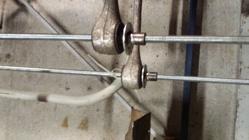
Last edited:
MGTSTUMPY
Active Member
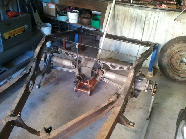
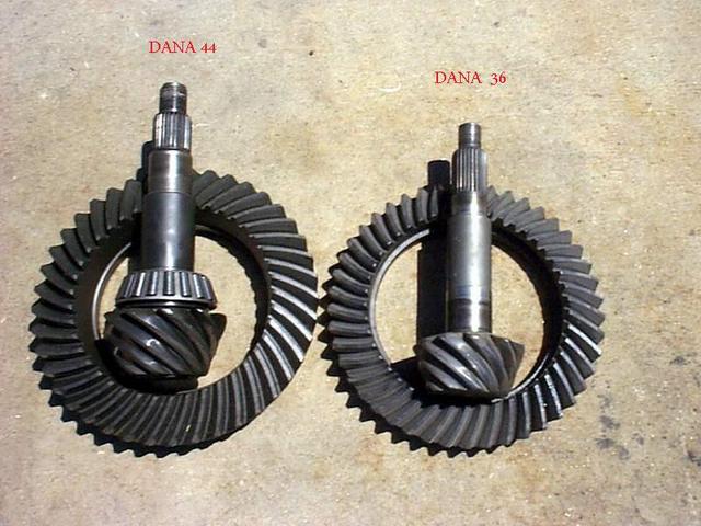
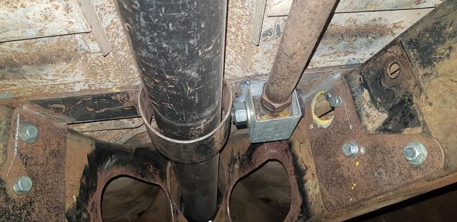
OEM C4 IRSs feature a 'C' beam (#18) bolted between IRS centre and transmission extension housing. This is eliminated and a triangulated torque rod / upper support fabricated in lieu. This prevents IRS from rocking up or down during acceleration and braking forces. I'd prefer a manual D44 IRS for strength, unfortunately it's cost prohibitive and outside my current budget.

MGTSTUMPY
Active Member
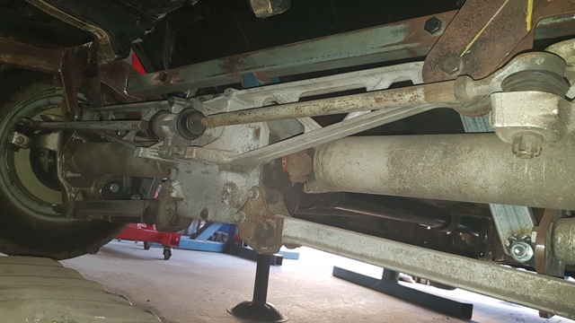
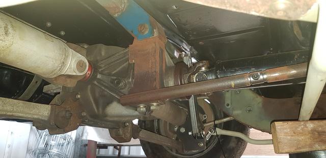
Sorry about being picture heavy but hopefully you can see how much actual fabrication etc went on when installing the IRS. The dog bones are recessed into the rear frame rails, the batwing brackets are gusseted and the pinion support / torque rod installed. The pinion support is also bushed with support bracket bolted through to differential case where OEM 'C' beam attached. The hidden internal bracket is captured by that visible external bracket off the rear cross member. The drive safety loop / torque arm is yet to be gusseted with the forward bushed end passing through a window in the gusset.


MGTSTUMPY
Active Member
Not seen is the profiled reinforcing bracket that captures the differential centre section, that bushed section is welded to bracket which remains with differential when the top bushing bolt is removed. Those nuts were also welded on the inside of that bracket and not left loose as they are inaccessible when assembled. Keep it simple, easy to service as a drop out if necessary. The bushed bracket was then cut and the top bracket profiled so it clears floor pan, hence the tapered end forward of the top pinion bolt. I've added bump stop brackets to the rear batwing gussets and will be similar on the front despite Shockwaves having built in bump stops. Some added piece of mind. I'm just finishing off the front shock pockets and sway bar support brackets. Next is the self levelling AirRide sensors and link bars on all four (4) corners.
 [url=https://postimages.org/]

 [/url]
[url=https://postimages.org/]
MGTSTUMPY
Active Member
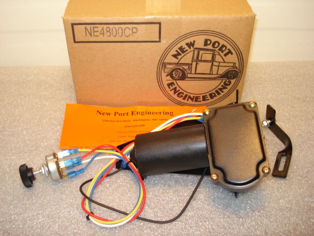
Under the dash I fabricated a support bracket that is a complete bolt in assembly; it holds the 90 degree pendulum brake assembly with hydroboost and master cylinder as well as Vintage AIR AC components. The entire complete assembly can be dropped out after removing 3 x bolts each side (Scuttle panel) and 4 x through firewall bolts. Simple and easily serviced if the need arises. It's very tight for space under the dash with remote brake reservoir, cowl vent assembly and Newport electric wipers (Direct bolt in) with radio in the dash and speaker filling up the last bit of available space. I still need to find space for the ignition coil (Using MSD through firewall connection) and engine ECM etc. I'll cross my bridges when I get there.
I didn't want through floor pedals or a [visible] firewall mounted MC assembly: A CPP 90 degree under dash assembly solved the problem and allowed me to have the pendulum pedals I wanted.
Rather than rechrome the old transmission towers I searched and located 2 x NOS Trico ones.


I didn't want through floor pedals or a [visible] firewall mounted MC assembly: A CPP 90 degree under dash assembly solved the problem and allowed me to have the pendulum pedals I wanted.
Rather than rechrome the old transmission towers I searched and located 2 x NOS Trico ones.
MGTSTUMPY
Active Member
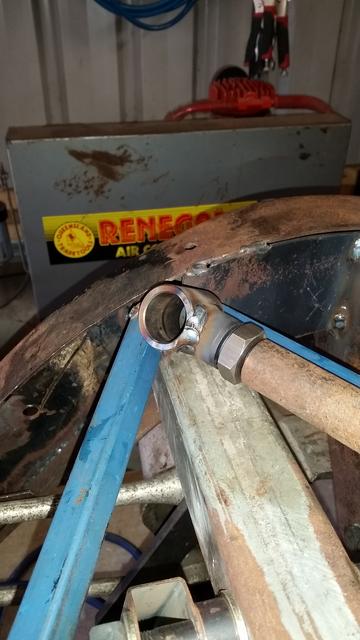
Here is bracket that captures IRS centre and lower torque rod. I need to bend the top tube slightly to clean floor pan, when completed it will look similar to a ladder bar with webbing reinforcements between top and lower tubes. To facilitate removal I'm using weld in roll cage connectors which disconnect after removing the HT cap screw bolt. A lot of strength in triangulation.
I had to replace both front door lower window sash channels due to rust, they weren't worth repairing. I'd previously bought new sash channel runs from Steel Rubber when I ordered all the window fuzzies. Another job done. Rusty Olds got some for his '47 convertible as well.


I had to replace both front door lower window sash channels due to rust, they weren't worth repairing. I'd previously bought new sash channel runs from Steel Rubber when I ordered all the window fuzzies. Another job done. Rusty Olds got some for his '47 convertible as well.
Last edited:
MGTSTUMPY
Active Member
Keith, I haven't retired yet however I'm running out of my accumulated leave and have just used all my long service leave (LSL). I'm now accessing my recreational (Holiday) leave balance which I've let build up over time. Whilst on leave I'm still accumulating LSL as well as sick and recreational leave. I officially retire in April 2019 when I turn 60, a legal requirement with my occupation. Nearly 40yrs in law enforcement so I've had enough. Lots of things to do and catch up on around the home etc etc. Deuce Days again in 2019 with John In Oz. House is too big so time to think about downsizing to a smaller house with a bigger shed. Almost everyone I know who have retired are busier now that when they were working full time.
I officially retire in April 2019 when I turn 60, a legal requirement with my occupation. Nearly 40yrs in law enforcement so I've had enough. Lots of things to do and catch up on around the home etc etc. Deuce Days again in 2019 with John In Oz. House is too big so time to think about downsizing to a smaller house with a bigger shed. Almost everyone I know who have retired are busier now that when they were working full time.Geez Mark I’d better get going on my Olds. I’ve really lost a complete year while my body man had it to do a “few” final things.