1946 Oldsmobile sedanette

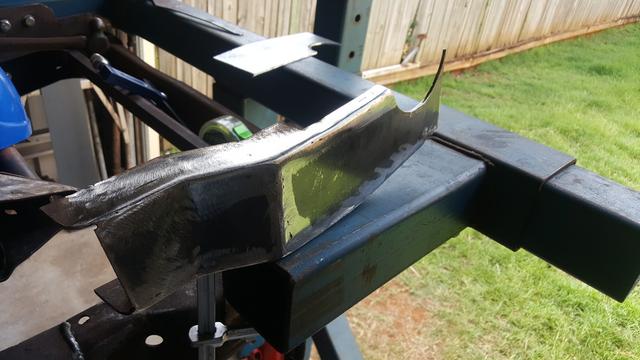
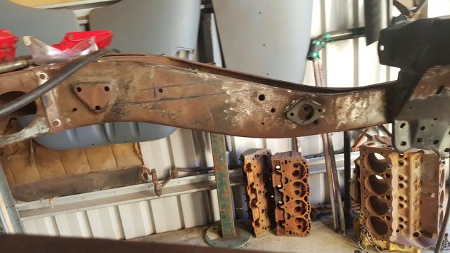
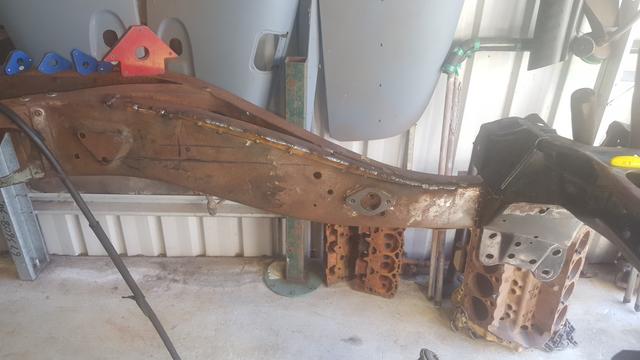
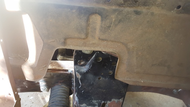
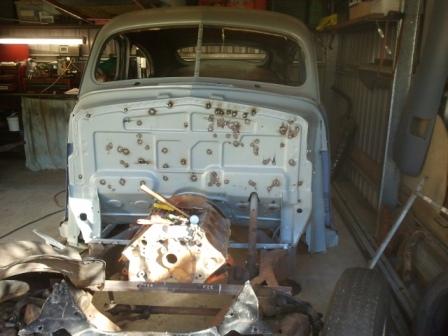
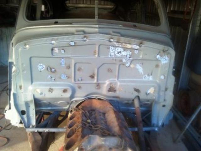
I loved the OEM pressing on the firewall so I welded up all the unnecessary holes for that clean look. Still a work in progress.


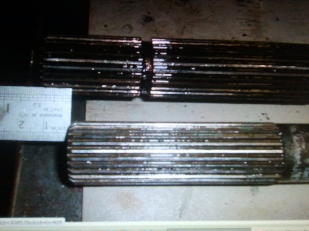
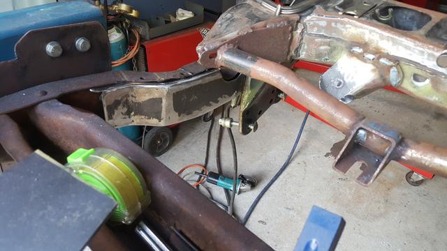
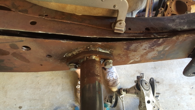
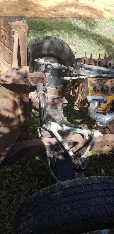
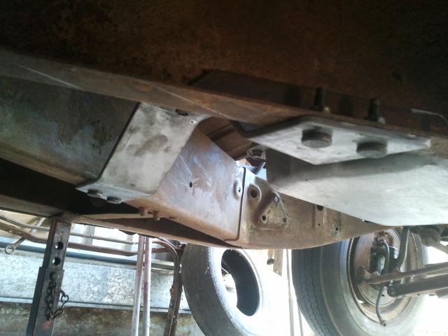
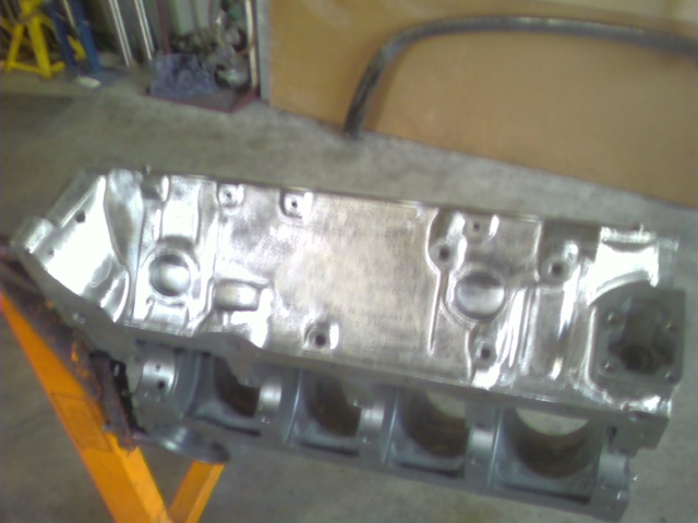
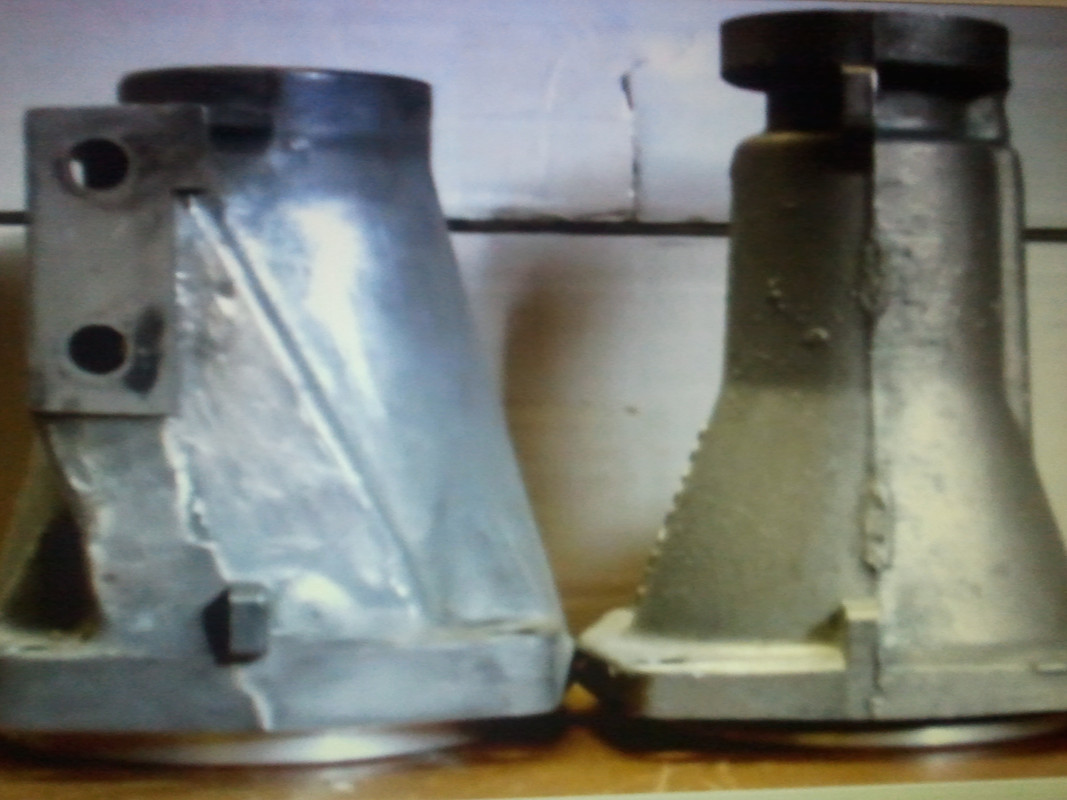
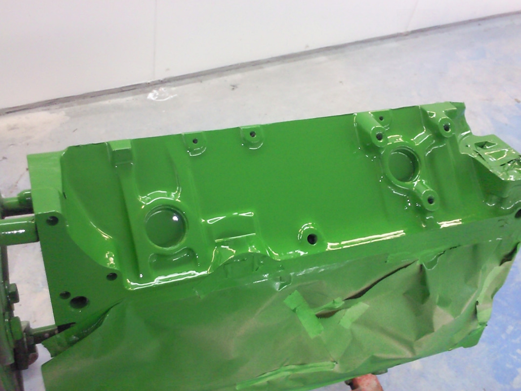
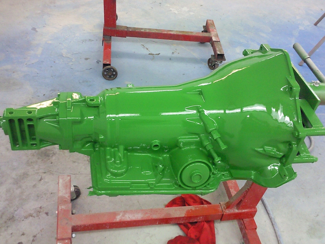
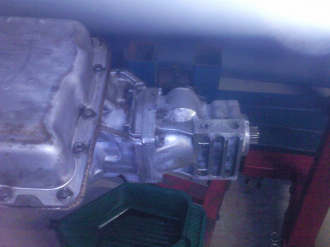
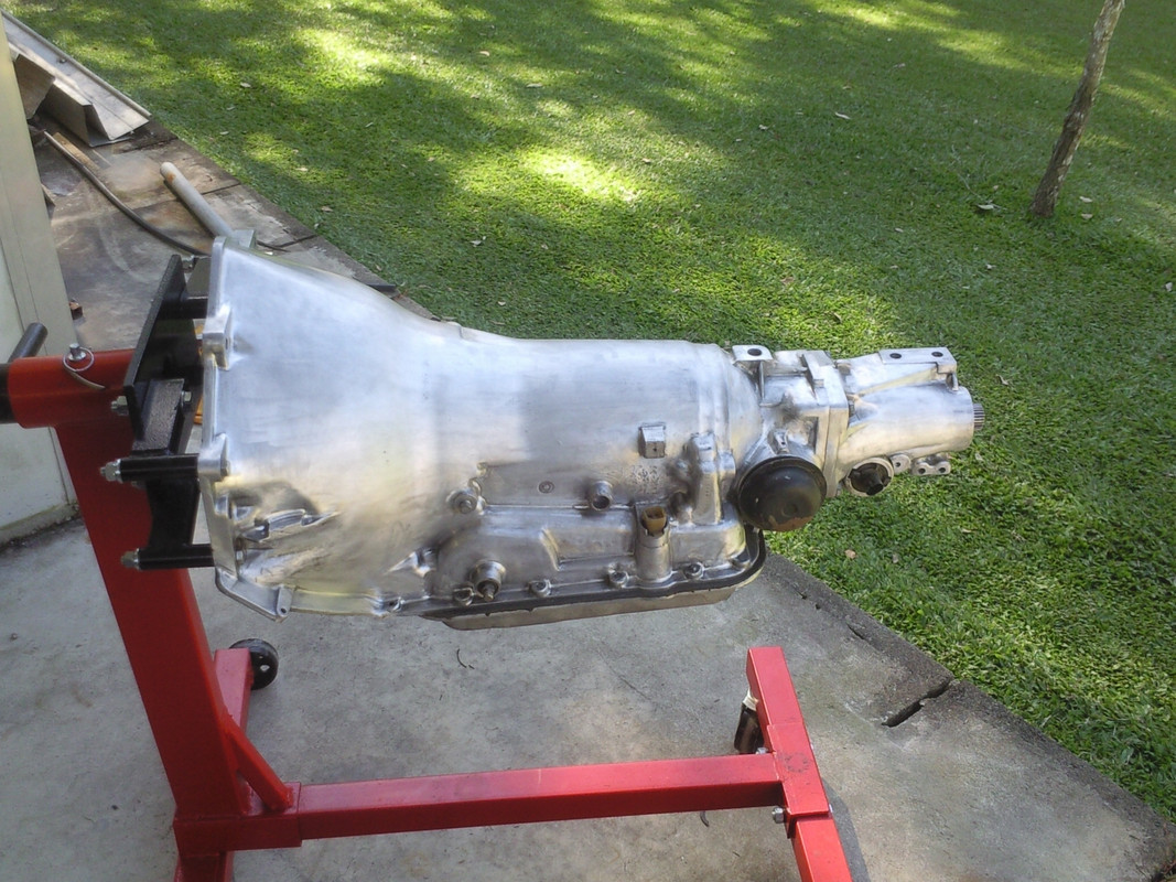
I linished the block and transmission case before painting. As the 700R came from a C4 Corvette I had to swap the extension housing and output shaft as I eliminated the OEM 'C' beam that bolted to IRS. Plus the Corvette case has no casting provision for transmission mounting. It was rebuilt and beefed up with extra internal goodies and shift kit:D


Fauxsmobile rocker covers to cover the top end of my SBC. John Deere green now however it should have been darker.
I had the OEM Corvette heads upgraded with larger valves, ported & polished. I'm using quality ARP bolts and other parts throughout drivetrain, top to bottom as well as upgrading to SFI flexplate and balancer for piece of mind. I'm also having a girdle built into the D36IRS (Auto) rear batwing similar to that in OEM D44IRS (Manual) to strengthen things up a bit since the Olds will be a big and heavy car.


As they've not available aftermarket I had to get new sill plates, running boards and boot scrapers reproduced. It took a long time to locate someone that could do them. Rubberwork was done by Kris ARNESON (http://www.runningboardrubber.com/contact_us.html) in McBride BC. Great work. A PITA sending things over not to mention the additional cost however I'd recommend Kris and his work.


The aluminum sills were reproduced by Steplates in Halidon NJ. Don did an outstanding job with laser etched pattern and Olds script.

 
Last edited:
I had the SS exhaust installed when the chassis was incomplete and a part roller. The forward IRS torque rod and bracket (Tailshaft loop) are yet to be finished. The exhaust has since been polished. I added some Doug's headers electric cutouts and turn downs (Dumps). Nothing hangs below the bottom on the frame and all you see of the exhaust is the tubing leading to the dumps as the rest is hidden behind frame X-member. I still need to have the final 1m from rear axle to back bar finished. Now that body is back on and gas tank in, I know where everything has to go for clearance. Since I'm using Fentons I had to move the engine mounts back as well as widen engine tube, allowing sufficient clearance otherwise outlets would be directly in line with tube. Hurst style front mounts won't fit due to low mount AC and PS. The engine mount plates have a rear reinforcing rib for strength

 
Last edited:
WOW! Whole lot of thinkin' goin' on! Everything looks well thought out and executed. thanks for the update -spectacular so far......
 
Good work Mark.......I am stunned that your running board covers are made in the small town of McBride BC which is 120 miles east of Prince George. Wow:)
 
Pendulum pedals and not through floor. Kugel bracket with hydroboost. Add the AC and space is running out, very tight with cowl vent , wiper motor etc. I think us Ozzies can put together a well thought out and well engineered car. As things are symmetrical I used the handbrake mounting brackets to support the complete under dash assembly which can be unbolted as a single unit, 3 x bolts either side and a couple of button heads on the firewall. You can see the widened engine tube (Sleeved) and low mount AC and PS brackets and why Hurst mount won't work. Also the offset engine mount to clear the Fentons.


Purchased some plates from my local DOT plus some vanity plates I also grabbed


All new crossed drilled and slotted rotors so I can stop:eek:

All new hubs as OEM sealed units were pretty worn out.


I still need to rebuild R&P and won't skimp on safety issues; brakes, steering or suspension
 
Keith, it's all done with smoke and mirrors and time lapse photography:D
Progress has been slow due to a shoulder reconstruction and carpal tunnel surgery to both hands :eek: They'll never be 100% however I'm stuck with them.
 
There is actually more detailed work you don't see there, considering you have been a cripple for a few months now you have banged that along pretty well.
 
Out with the old and in with the new, measure twice, cut once. I fabricated a jig to ensure that all the C4 components would mate up to the OEM mounting points; core support, front bar, etc once wheelbase and diagonals were correct. The OEM inner sections were removed to expose the noutside frame which was angle cut to accept new frame rails sections. These were reinforced from behind with fish plates for strength and integrity. A plasma cutter and cut off saw made short work of things.

 
I've oversimplified exactly how much work went to adapting the C4 suspension and fabricating new inner and out frame rails. The outer rails had to be widened slightly to suit, hence the pie cuts, the wider front suspension. Accordingly the inner rails were moved forward and out on the centre X-member legs to match outer frame rails so it all appears OEM. I then had to reinforce the front frame rails internally to compensate for R&P reliefs as the entire front sheet metal and core weight attaches forward of this point. There are also reliefs for front Shockwaves that require new stronger upper shock brackets. The rear of the front cross member is to be gusseted vertically to the inside frame rail as per engineers requirements given that the OEM C4 legs aren't being used. This is to counter braking forces and prevent it rocking under load. It should ride well with new IFS!
OEM front frame rails were single 'C' channel however I fabricated new inner 'C' channels that slip inside and box the entire front forward of the front cross member. All weld it will be strong with minimal torsional twist and strong enough to hold the weight of the entire front end and tie the frame to the front cross member. The lower core top hat section was also boxed for strength. All the OEM rivets that were removed were replaced with HT button heads bolts with lock nuts. I'm thinking of welding the centre and linishing so they appear to be OEM rivets?


As the inner frame rails came forward and out they no longer matched the outer frame rails so I had to pie cut along the edge and insert a filler piece to maintain OEM profile, allowing a better fit to OEM outer frame rails. If I didn't mention it I doubt that anyone would even know what had been done. Plus a lot more strength over a larger area. A couple of fillet welds and voila, all done.
 
Last edited:
Thanks for keeping us in the loop. Great looking project has my attention. :)
 
What I didn't mention before was that the C4 IFS I purchased came from a local wrecked RHD car. I had a damaged LHD cross member thrown in for the R&P mounts along with a good R&P as I didn't want a RHD car. It took a bit of work to remove the RHD mounts and reconvert it back to LHD however since I've previously done a couple of RHD conversions,this time I went the alternative [LHD] route. More measuring with verniers, levelling etc etc to get things right. He's another RHD C4 front suspension I bought from another wrecked car that I sold interstate with the C4 IRS for a '57 Chevy conversion. It's a rear steer LHD GM from memory that is used for RHD front steer conversions; perfect for RHD conversions, correct geometry, width, rack ends and input shaft etc.
 
Last edited:
WOW ! "You're a better man than I am, Gunga Din!" Nice work.
I'm thinking that too many birthdays and the onset of winter is my reason for a sabbatical, but that might just be an excuse, year around summer would help (maybe). :)
 
'Gunga Din', geez I can't remember the last time I heard that old Ozzie phrase! As old as 'Cobba (Mate) from the early 20th century. I might add that the steering above is NOT in phase and the RHD conversion was completed by a so called 'Reputable' interstate Corvette business. The steering shaft was poorly welded under the rubber boot and couldn't be seen. What an inferior weld. :eek: I'd hate to depend on the workmanship with my life!! If that's the quality of their work I wouldn't touch them. I doubt that would pass any load test (Nm).

My intermediate shaft will be collapsible as per engineer requirements, that way I can use the OEM column with OEM Hydramatic shifter. I'll need to modify the gate for later Hydramatic.
Here are a few shots of rolling body with new IFS and core support. Inner aprons need slight work to realign opening with new suspension. I sectioned the RH R&P mount to provide clearance for AC compressor with recesses on top of cross member for AC mounting flanges.

 
These are the low mount Alan Grove AC and PS brackets, out of sight and hidden down low. Those folded brackets on cross member are lower control arm Shockwave mounts that I fabricated. The available Ridetech brackets DON't fit Shockwaves.


Down here all outboard seating positions require retractable lap sash seat belts so I've fabricated all new mounting plates to spread the load at mounting points plus adding centre seat belts to front and rear seats. To reinforce the upper 'B' pillars I inserted 150x30x8 flat plate,drilled and tapped for upper mount. This was welded to framework. The larger plate is 2mm with bottom reinforcing being 3mm with 30mm boss. It was welded together and plug welded to inner frame work behind 'B' pillar. The boss was fully welded to tie it all together The retractor mounts to the boss. It's discreet and nice and solid, and won't flex under load. Here's the engine and transmission mounts. Nothing hangs below lower flange of frame. Stout 100x6 flat bar with reinforced frame flange.
 
Old steering column tube and shaft was cut with a new floor plate fabricated. Collar on inner side of shaft rides on bearing in the delron bushing. Not seen is a large Circlip on the outside under delron bush. Inner column shaft doesn't move up or down and grease nipple allows bearing lubrication if necessary. It can be swapped out for a grub screw later.Bearing is from a local Ford column, 3/4" ID which matches shaft OD. End is machined for 3/4DD Flaming river vibration universal joint that connects to collapsible intermediate shaft.