| |
Laying
out additional odds and ends
by Frank Colgoni |
| |
|
|
|
We mentioned in the dashboard article that there was a lot planning
involved in dash layouts and placement of all the bits and pieces.
A similar amount of planning went into the positioning of whole
range of other necessary odds and ends.
Starting
in the trunk area between the main cabin and the trunk proper,
we had numerous items to place. The end result was not the original
configuration, as we've had to make a few changes to accommodate
additional items and to make things easier to access down the
road (and maybe on the road).
Once
again, the smaller confines of a '32 coupe body requires judicious
use of space. Fortunately, we've been able to accommodate everything.
In the pictures below, you'll see the positioning of the main
fuse panel, the fuel injection interface panel, the computer,
a windshield wiper motor, the Air Ride compressor and tank and
a battery box. We have also left room for audio components.
On
the floor, a number of provisions were also made for wiring, seat
mounts, emergency brake handle, shifter boot and finally the accelerator
pedal.
|
| |
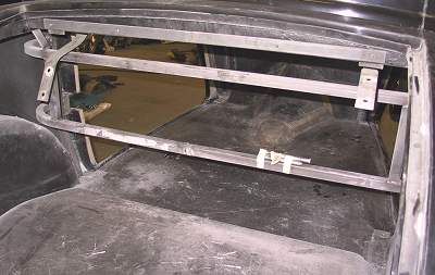
This is a view of the steel structure separating the trunk from
the main cabin,
as it was when we received the body (looking through the trunk).
|
| |
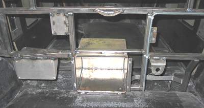
This shows the alterations to the steel required to position various
components
associated with our electrical system and Air Ride rear suspension.
|
| |
This is the view from the cabin side. |
| |

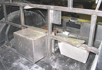
This is the way it looked populated with the components (some changes
have
since been made but we'll deal with that in a later article). |
| |
On the left we have the Ron Francis Wiring main panel with the Air
Ride compressor on top. |
| |
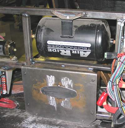
In the middle is a custom, ventilated, battery box with the Air
Ride tank on top. |
| |

On the right is the The Detail Zone's Telorvek fuel injection wiring
distribution panel
and the Specialty Power Windows windshield wiper motor. |
| |

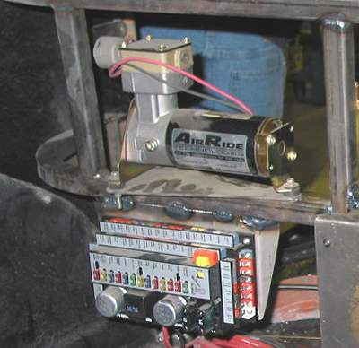
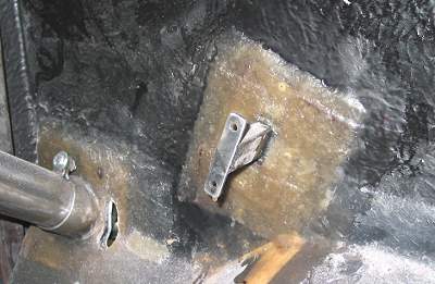
In this photo, the arrow is pointing to the bracket / cradle for
the computer. |
| |
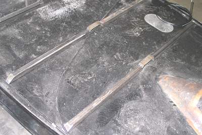
Originally, we thought that we would need two braces for the seat.
You'll notice that the braces
have been notched to allow wires to pass through the centre and
that they fasten through the
body into the frame. This is done for two reasons: it keeps the
floor clean and free from
unnecessary holes and it provides for secure anchoring for the seat
and seat belts without
having to places extra reinforcement under the body. |
| |
Later, after choosing a seat frame (later article also), we eliminated
the front brace and
laminated a couple of fabricated wire troughs and a trans tunnel
extension to the floor. |
| |
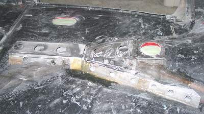
This rear trough will direct wiring and emergency brake cables through
the middle of the cabin.
The cables will enter the cabin just in front of the rear wheelwells.
The emergence brake handle
and ratchet mechanism will be totally inside the car. Again, to
eliminate a hole in the floor.
This also keeps the mechanism as new for the life of the car. If
you look closely, you can
see a small, two-holed bracket for the cables at the right end of
the trough. |
| |

The front trough will direct the wiring to the under-dash area,
firewall and, for the starter,
through the two holes at the extreme right. On the driver's side
of the trans tunnel extension
is the bracket for the emergency brake handle. |
| |
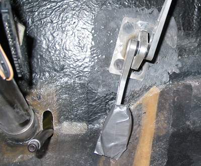
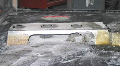
In this photo, the throttle pedal had been mocked-up with an extension
bracket
"lightly" glassed to the floor. The bracket provides for
extra clearance to permit carpet
and underlay. The angled installation puts the pedal in the right
position and matches
the angle required for the driver's foot. |
| |
With the location confirmed, the accelerator bracket is glassed
permanently in position. |
| |
|