| 1961 PV544 Project - Update 12 |
By Frank Colgoni To reacquaint you with the scenario regarding suspension and steering, the main goals were to get the car lower (see Update 9) and to improve on braking. In terms of lowering the car, there are no really straighforward options to lower the car using the stock setup (like different spindles for example) although many people use shorter springs to start. Relative to brakes, there is a methodology available that involves a swap to disks by utilizing front brakes from the Volvo 122 and relocating the shocks to the front (components not commonly available however). As a departure has been made from an inline engine to a "V", the other complication (domino effect) is that the existing solid, one-piece steering column won't work (it's a jointless column). After extensive investigation into options that would satisfy the goals and get around the column issue, it appeared a complete front end replacement was in order. It was at that point that I involved Grant from Schwartz Inc. |
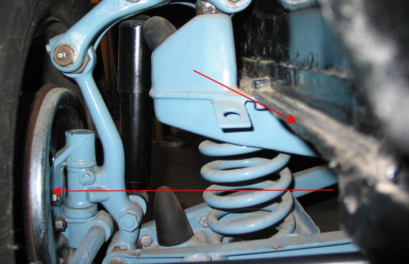
Below: The original front end. The dotted line is the path of the original solid steering column. The arrow points to the location where the end of the column/steering box mounts. 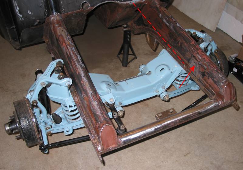 |
Below: For reference, this was the stock suspension height. The top arrow is the bottom lip the frame rail. The bottom arrow runs through the centreline of the spindle. |
Below: With the new plan in place, the parts necessary to build a front end from scratch were sourced from Horton Hot Rod Parts (Heidts and Welderseries components primarily). At this point, Grant has the crossmember assembled and sitting in position. 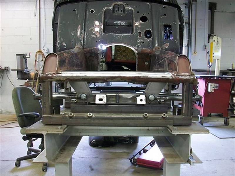 |
Below: This is where things start to get tricky... The dotted red line is the area Grant felt would have to be removed to accommodate the upper arm plate and coilover mount. Needless to say, this would recquire re-boxing and reinforcement. 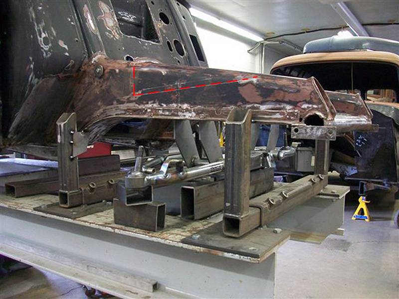 |
Below: Here are the rails after the material was removed. At this point, it's not hard to visualize that building the factory rail strength back in would be challenging - not impossible but challenging and likely not attractive. Another strategy developed. 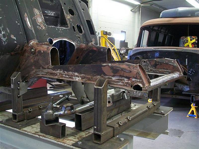 |
Below: Stage one of the new stategy. the forward portion of the rails have been removed entirely. Prior to that, indicated by the arrow, the spreader bar was fixtured to maintain its position (critical for front nose and radiator placement - and then inner fenders, front fenders, etc.). 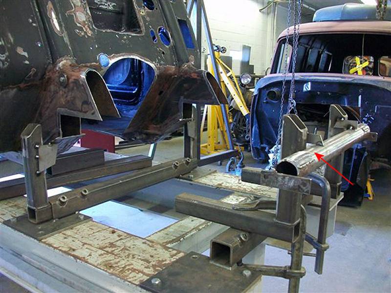 |
Below: A new rail was fabricated from rectangular tubing. The inner side lines up with the inner side of the original rail. The arrow points to a void that will need to be filled and used to further strengthen the joint between the new rail and existing. 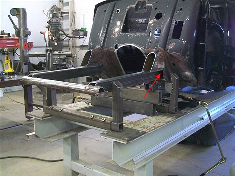 |
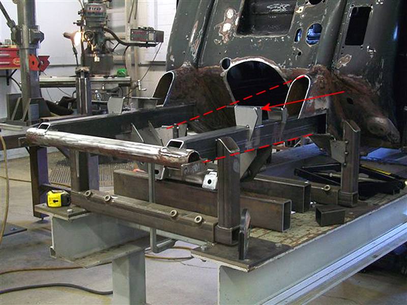
Below: The dotted lines portray where the original rail would have been. The arrow points to the upper arm plate. This further illustrates how much of the rail would have had to be removed to accommodate this. |
Below: Further along in the mockup of the suspension. For comparison to the second photo in this article (above), you can see where the centreline of the spindle is (top dotted line) when compared to the lower dotted line which was the centreline of the original suspension. 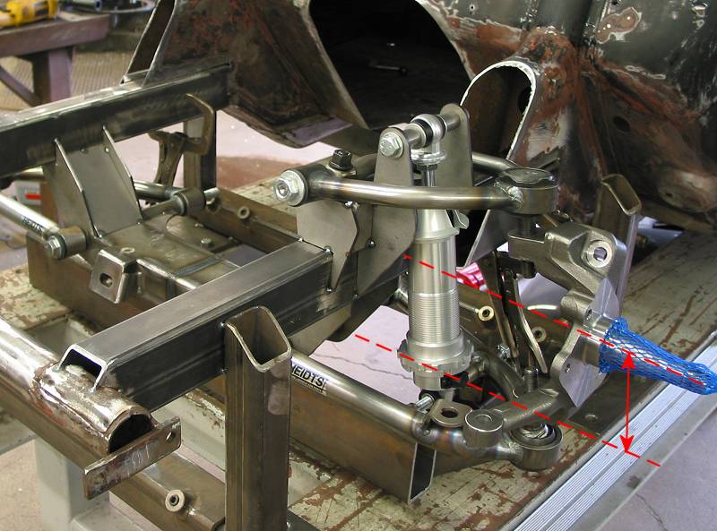 |
Below: The left arrow points to the extra piece of tubing that will be added to complete the junction of the two rails. The right/lower arrow points to the weld indicating that the crossmember was narrowed for this application. 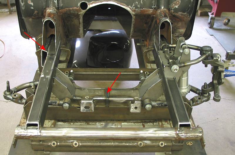 |
Below: Another photo of the new rail where it meets the existing. The arrow points to the rear fastening point of the inner fender panel. Fortunately, its position is unchanged. 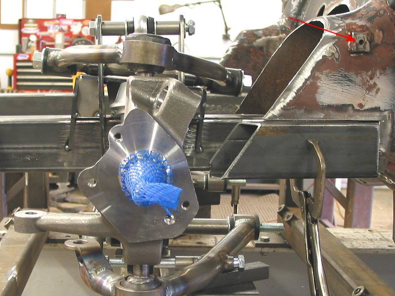 |
Below: The completed junction of the old/new rails with end caps (arrows). Once again, the dotted line is the approximate location of the top of the original rail. 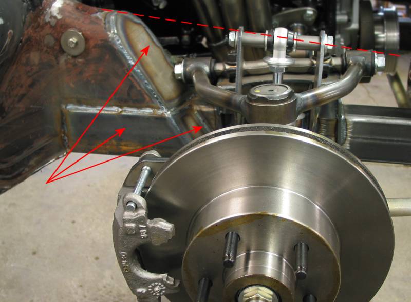 |
Below: Narrowed rack (Forrest and Forrest Racing). Inset photo: Pieces that were removed.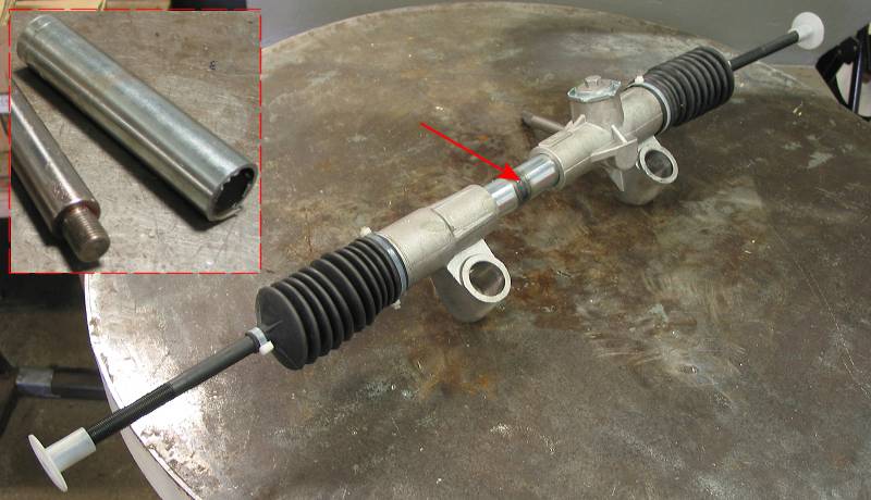 |
Below: Detail - passenger side 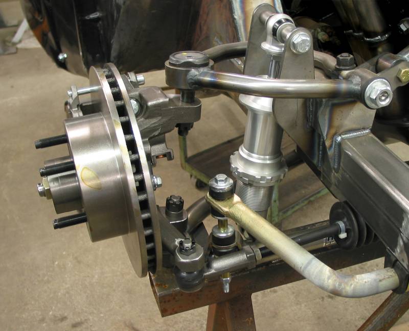 |
Resources Next: Rear end / suspension |