As
you may know, a 1932 Ford tank, when mounted in the stock postion
at the rear of the frame rails, is in full view. That is, it's
not hidden behind a body panel or apron. Depending upon your preferences,
you can go with a poly tank, stainless, an original shaped tank
or a combo and incorporate a cover which simulates the stock shape
on top.
In
our case, as is the case with most (but not all) full-fendered
cars, we are placing the tank in its stock position and needed
a tank compatible with a fuel injected application - preferably
with an in-tank pump which pushes fuel rather than pulls it. The
following explanation is courtesy of Popular Mechanics:
"Submerged Fuel Pumps – How They Work
Electronic fuel injection systems won't work at all unless they're
force-fed a constant supply of fuel under fairly high pressure.
In the early days of EFI, electric pumps could be found outside
the gas tank. But they faded from view because in-tank pumps held
many advantages.
In-tank
pumps are quieter and tucked away from engine heat and weather-related
corrosion. Perhaps most important, they pressurize the fuel along
the entire length of the system. Because higher pressure raises
the fuel's boiling point, vapor-lock is virtually nonexistent
in vehicles with an in-tank pump. It's also easier for a pump
to push a liquid through a line than to pull it, so in-tank pumps
are smaller and lighter. The whole assembly sits in a cup-shaped
fuel reservoir that's usually fastened to the bottom of the tank.
Unused fuel spills from the return line into the cup whenever
the pump is running. The filled cup assures that sufficient fuel
surrounds the pump pickup during braking, cornering and acceleration,
even when the tank is near empty.
Electrical power for the pump usually comes from a pump relay.
Turn the key on in a car with an in-tank pump, and the relay switches
the pump on for a couple of seconds, filling the cup reservoir
and pressurizing the system. After it travels up the pickup tube,
it enters the inlet side of the pump, where it rushes directly
through the pump motor to cool and lubricate it. From there, the
fuel goes into a geroter (sliding vane) or roller vane pump assembly,
where it's pressurized. Yes, that's right, the fuel runs directly
through the motor, where electricity sparks across the motor's
brushes. If you think back to your high-school chemistry class,
you'll recall that combustion (or, in this case, an explosion)
requires three things: fuel, ignition and oxygen. Fortunately,
oxygen is not present in the fuel pump, so there's no ka-boom.
Before the fuel exits the pump into the fuel line, it passes through
a one-way check valve. The valve keeps fuel from draining out
of the line and back into the tank when the pump is off"
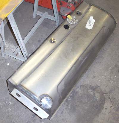
To
get all we wanted from a tank, we chose a Tanks 1932 Ford tank
equipped with a high volume fuel pump having both feed and return
fittings. The tank bottom is not identical to the bottom profile
of the stock '32 tank because of the requirements of the in-tank
pump. This isn't an issue as it can't been seen behind the frame
horn covers / fenders.