More Frame Work - Crossmembers and C-Notches

by Frank Colgoni

With our boxing plates in place and with the frame still in the fixture, crossmembers can go in. Starting up front, as we have pinched the rails, an alteration must be made to our aftermarket crossmember relative to the width and the existing provisions for rad mounting (rad mount pads with slots) will have to be changed also. As a rad will be custom made for this car, that shouldn’t be an issue as we’ll provide the appropriate specs.

After shortening the crossmember to the required width, the crossmember can be tacked in place then finish-welded (mindful of caster angle). Note: Aftermarket crossmembers are stamped with caster angle established relative to the rad mount pads. See FYI below about caster.


Here's the front crossmember in place -
shortened with reworked rad mount pads

The angle built in to the crossmember takes care of caster.
The rad mounting pad is at 0 degrees.

With the front crossmember in, intermediate
and rear crossmembers can be installed
FYI and to digress slightly, some info about caster, camber and toe in:

“Caster is the backward or forward tilt of the kingpin measured in degrees from true vertical. A backward tilt of the kingpin, which is usual in most beam or tube axled rods, is called positive caster. The angle of caster effects the steering, e.g., positive caster causes the front wheels to run straight and influences the return to center of the steering wheel. Negative caster causes the steering to be ‘touchy’ and harder to control at speed.”1)

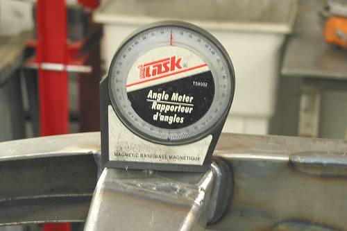
Conventional wisdom suggests that caster be set at 6 degrees (positive) although I have seen 5-7 suggested.

“Camber is the inward or outward tilt of the wheels, measured in degrees from true vertical, when viewed from the front. Positive camber is when the wheels lean out, negative when the wheels lean in. Excessive camber will cause premature and uneven tire wear. In most hot rods, the camber should be between zero and 1/2 degree positive and in most cases the camber is engineered into the axle at the angle at which the kingpin hole is machined into the kingpin boss.”2)

As we will utilize an I-beam axle, the above applies to us. While we’re discussing front end specs:

“Toe-in, toe-out is the angle at which the wheels point when viewed from the top. Toe-in is when the wheels point slightly toward each other at the front, toe-out is when they point away from each other. With rear-wheel-drive, the leading edges of the tires tend to pull away from each other, so they are set with toe-in to counteract that tendency.”3)

Back to conventional widom, “hot rods with radial tires should be set with 1/8-inch toe-in. Hot rods with bias-ply tires should be set with 3/16-inch toe-in. Adjustment can be made by screwing the tie rods ends in or out.”4)

Note 1) - 4): excerpted from So-Cal Speed Shop and is meant as reference only.

Back to The Fabrication
Dream Machines then fabricated and installed a rear crossmember (set up for coilovers) and installed the top portion of a Horton centre section (enough to stabilize the frame). A Welder Series forward 4-bar bracket was added then the frame was removed from the fixture and flipped over.

Given that we are going for low ride height, the frame required notching front and rear. The front notches mimic the caster angle.

Before notching the rear, Dream Machines fabricated a “dummy” rear axle housing to hang using 4-bars and spacers to simulate coilovers at ride height. Welder Series' 4-bar axle brackets were added and the dummy axle was attached to the frame with the rest of the Welder Series' 4-bar kit. With the axle swinging, the arc of travel was established and rear c-notch position was established.


Rear crossmember with provision for coilovers

Detail of crossmember

Notice that the boxing plate welds have been dressed adjacent to the
crossmember. This will continue along the full length of the frame.

Front notches with spring sitting in position

Welder Series forward 4-bar frame barcket installed
Dream Machines added the hole for drainage
should water accumulate in bracket valley.


Dummy axle housing in position prior to notching rear

Note the bushings in the end of the dummy axle housing. These will be used
with a dummy axle/wheels/tires when we fine tune ride height and
in/out spacing of the wheels relative to the body. After we establish the
in/out spacing, we can establish rear end width.


The beginnings of a c-notch plate

Notch cut out and plate ready for welding

Completed notch

Dummy rear end assembly completed

Resources:

Next Up - Front end , wheels and tires and establishing ride height
TOP