| 1961 PV544 Project - Update 16 |
Let There Be Heat By Frank Colgoni Having heat in this vehicle was never not an option. That is, given heat will extend usage at both ends of the seasonal spectrum, we planned on a heat solution. To give you an idea of how heat was supplied in a stock Volvo PV544, have a look at the photo below. |
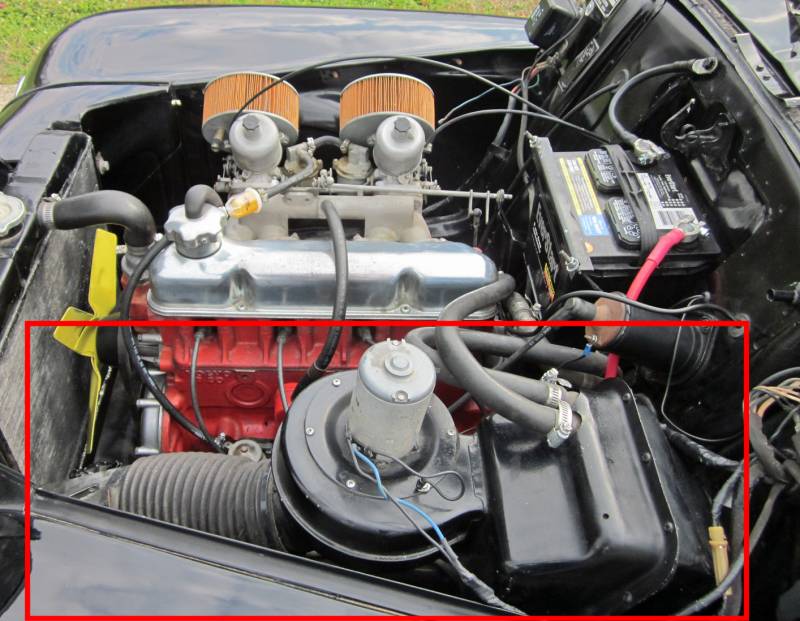
Below: The stock PV544 had an inline 4-cylinder (B18 version shown). Being an inline engine, there was plenty of room on both sides - for intake/carbs/exhaust on one side and the steering column and heating system on the other. Everything inside the red rectangle is related to the heating system - starting with fresh air intake, then an electric fan, then the heater core. The only thing inside the vehicle is ducting.
|
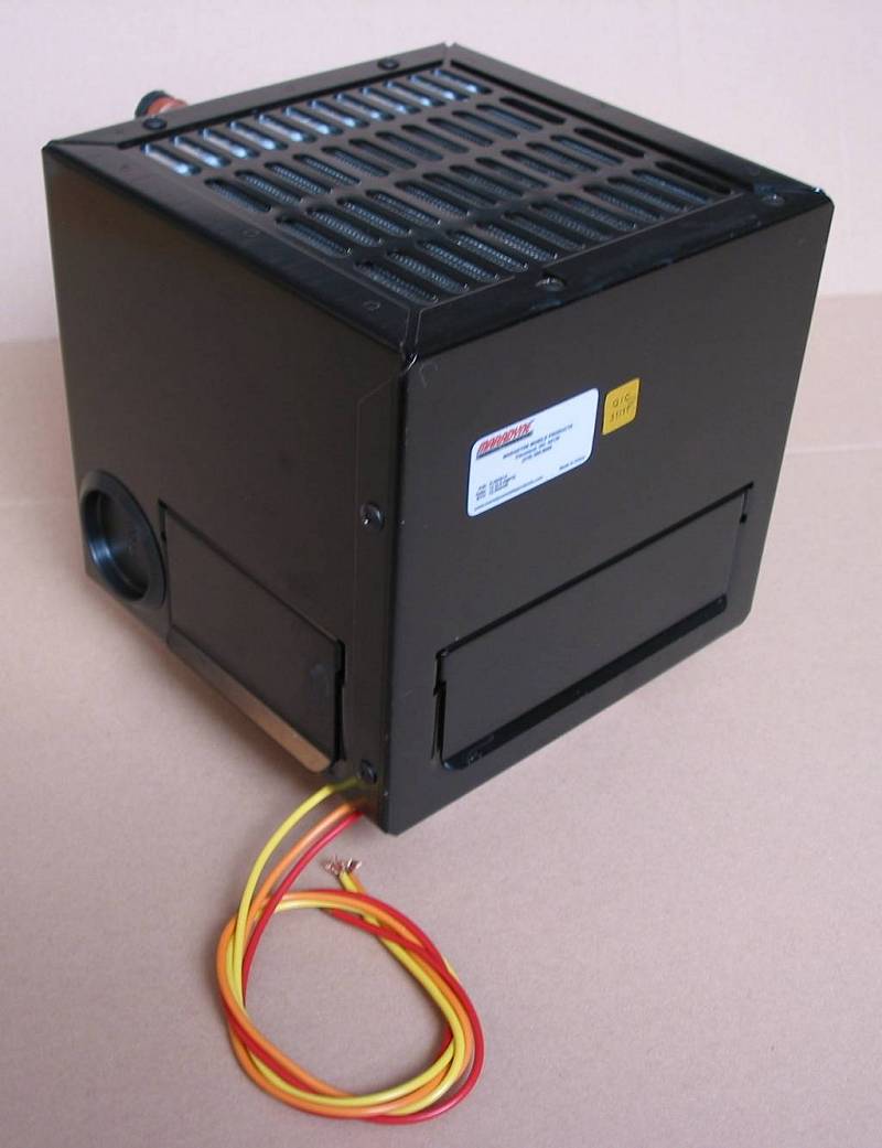
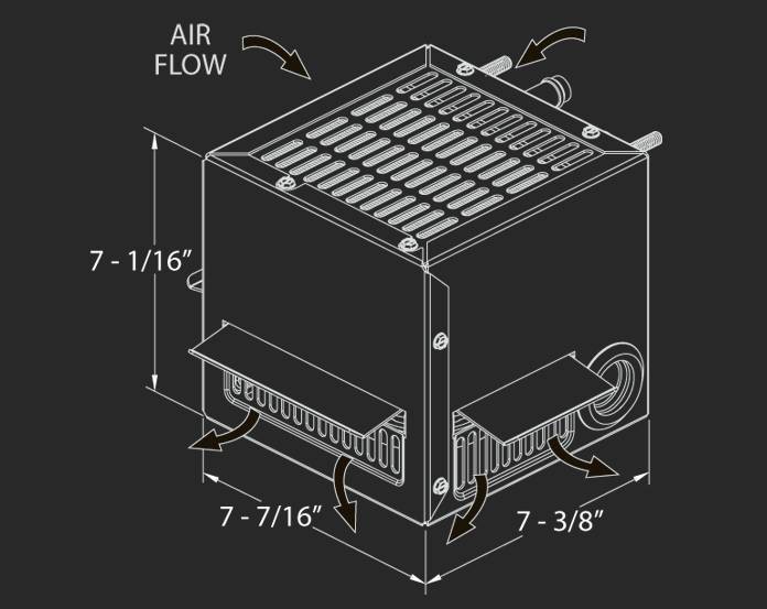
So, when we committed to a "V"-style engine (see article 10), one of the things that would have to be moved and re-imagined was heat. Fortunately, a slick solution was found in relatively short order. Specifically, a Maradyne 5000 coolant-fed heater with a 12V fan (Visit their site HERE for more info about the unit and available accessories). About the "5000": It's a compact design (essentially a 7" cube) with a 22 ga. steel shell. It has a two-speed fan that draws only 3.1 amps yet delivers 12,500 btu of heat. Coolant passes through an internal tube/fin core and with heat exiting through three openings (front and sides) and / or optionally through round ports that adapts to defrost ducting. |
Below: Overall view with the delivery vents closed. The defrost duct (plugged) can be seen in the bottom left. There's a second port on the opposite side along with another delivery vent.
|
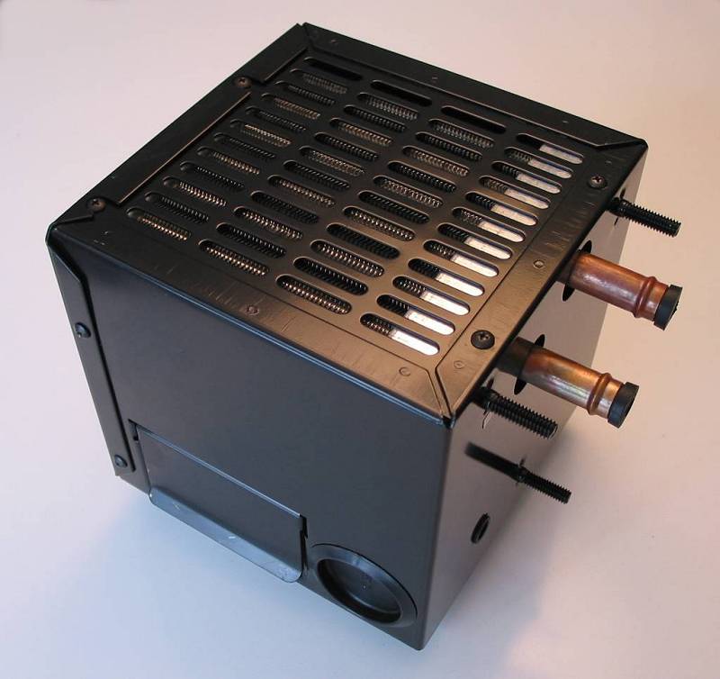
Below: A view of the opposite side and the back showing mounting studs and coolant inlet/outlet.
|
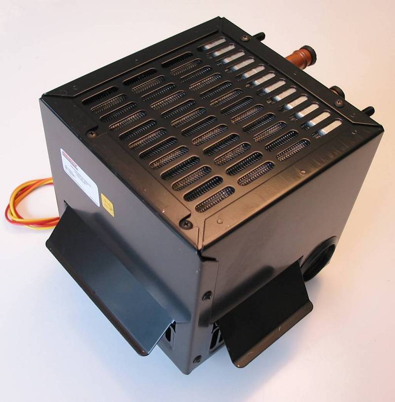
Below:Showing the delivery vents in an open position.
|
Below: Actual Dimensions
|
| Our plan was to mount the heater under the dash on the passenger side just off centre in order to avoid a conflict with the hood locking mechanism arm. In order to achieve this, it will be necessary to lose the glove box. This is a sacrifice we're willing to make and it may also free up room for our wiring panel. One of the obstacles we have to overcome is the slope of the firewall. |
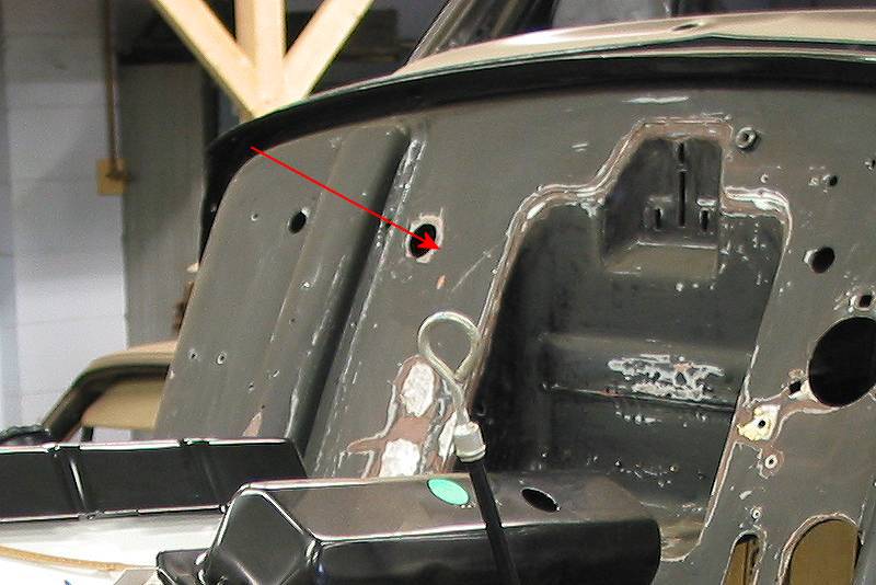
Below: The heater will mount behind the firewall area indicated by the arrow. The slope becomes obvious if you compare the vertical of the vacant battery box area compared with the balance of the firewall. A bracket will be required to correct for the slope.
|
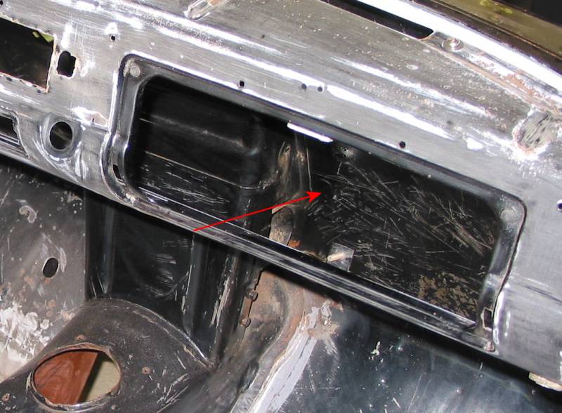
Below: The arrow points to the approximate mounting location viewed from the inside. The glovebox door has been removed.
|
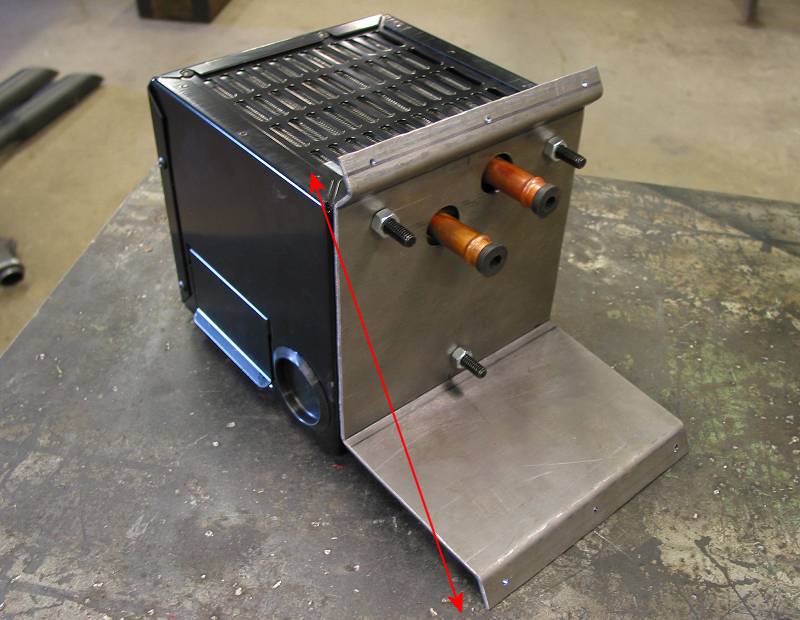
Below: Schwartz Inc. bent up this bracket to compensate for the slope of the firewall which will result in level heater mounting. The arrow illustrates the firewall slope.
|
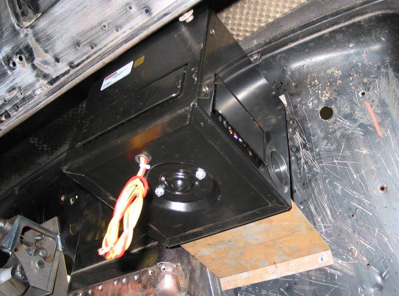
Below: Here is the heater in position under the dash. There's plenty of room above for our wiper mechanism and the passenger side defrost outlet.
|
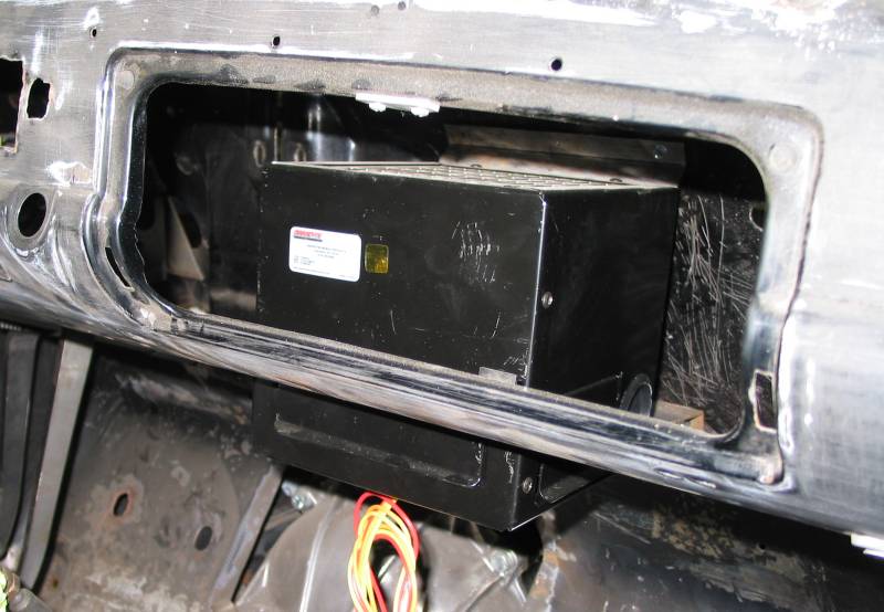
Below: The heater viewed through the glovebox door opening.
|
There will be more on the completion of our heating system during final assembly. |
Resources: Next: More on steering / pedals |