(SOLVED) How to verify if I have 1-wire or 3 -wire Alternator?

58chev

Well-Known Member
Supporting Member
I have a AC Delco 10SI Alternator, AMP unknown, that was purchased about 15 years ago and I can not remember if it is Internally or Externally Excited. :confused:

Is there a way to tell which it is?

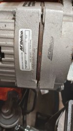
The numbers are somewhat worn out

At best, this is what I can find online:

10SI, 63 amp, Clocked at 3:00 (AC-DELCO # 321-39, Lester #7127-3)​

Tell the auto parts counter person that “The alternator is for a 1978, Chevy Camaro, 8cylinder 350engine, with air conditioning.”

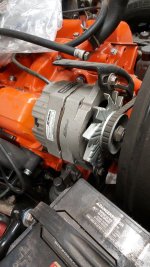
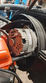
20220219_111809.jpg 20220219_111815.jpg 20220219_111826.jpg

 
Thanks Keith, but that still doesn't tell me how to differentiate between the two.
 
And I cannot remember and have installed three one wire units. Have to go thru snow to the back shop and check my Chevy
 
But your first link states that a 3-wire alt is also internally regulated.

I found the following this morning while trying to figure this out. Did not find this before making my post.

https://www.thirdgen.org/forums/electronics/767731-10si-alternator-internals-drop.html

I just need to check the regulator on mine to see if the pins are shorted together or not. (pictures in the first post of the link)

sofakingdom:
The regulator with the pins shorted together is an aftermarket or marine one, designed to make a "one-wire" alt. This is of course very easy to connect... it doesn't require any connection at all, except the big wire that charges the batt... but suffers from many shortcomings. Notably, one of the 2 connections is the "sense" lead, which is the one that the regulator tries to maintain the same voltage on at all times; it's usually, but not always, hooked up to some central distribution point well downstream of the batt, to allow the alt to maintain the voltage at that point constant, rather than letting it be affected by voltage drops in wiring, connections, etc. The other pin is the "idiot light" pin, which also serves as the "excite" or "command" connection. It receives power from the switched side of the ign sw, through the "Alt" or in these cars the "Choke" light bulb, with the bulb connected in such a way that when the ign sw is On but the alt is not producing power, the bulb lights up. One side of the bulb is connected to switched power, and the other to that pin; when the alt is charging, it puts 12V on that pin, which makes the bulb go out since it then has the same voltage on both sides of it; but when the bulb is powered from the ign sw and the alt is NOT charging, either because it's dead somehow or because it's not turning (engine is not running, belt is broken, etc.), that pin is grounded, in which case there's 12V across the bulb, so that it lights. Additionally it carries a small amount of current into the field winding of the alt, starting it up before it begins to charge, in case there's no permanent magnetism built up in the core iron of the rotor... since the field gets its power from the alt output via the diode trio, if the alt never starts producing power on its own, it will … never start, which is why it usually needs that little bit of external "starting" excitation. Which is why often your batt will go dead when the bulb burns out: the alt never "knows" that the ign is turned on, and therefore never charges. Not all cars have a bulb; some have a resistor instead, and some have both. In the ones of our cars with a carb there's also a relay in that circuit that controls the choke heater, connected such that the choke heater does not receive power unless the ign is on AND the alt is charging. If the alt is NOT charging, the choke heater will NOT get power, meaning it will stay on, meaning the car will have VERY high emissions, which apparently the factory or maybe da gummint thought was a more important failure to warn the driver about, than the batt not being charged and being about to die within a matter of a few minutes. Priorities.
The extra red wires and the extra screw inside the one in #3 & #4 are also not "factory". Not sure what all that is about. Ignore all that. Don't bother trying to decipher or duplicate it. Throw everything in that setup that isn't EXACTLY like #2 into the trash and don't look back.

The setup with the resistor - the object in #2 with the red straw pointing toward it - is the most common "correct" one. The aluminum assy inside it with the fins and the 3 winding terminal connections and the stud for the big red wire is the main rectifier. The alt itself is a 3-phase Y-connected AC generator, and that rectifier has 6 large diodes inside it, that convert the AC coming from the windings to DC. The small black thing with 3 leads that also connect to the 3 alt winding terminals, and the one lead that goes to the regulator, is the "diode trio"; it has 3 much smaller diodes, that also of course convert AC to DC, and the result of that powers the regulator and the field (rotor) winding.

If your car is still wired as it came from the factory, you need an alt like photo #2. If you go the parts store and buy a new regulator, brush set, diode trio, and bearings for it, esp the front bearing (part # 6203, with whatever suffix and or prefix whichever mfr uses to indicate 2 rubber seals), you will have, in essence, a brand-new alt. You could replace the rectifier as well if you felt like it but those almost never go bad. Most often the rear bearing is fine and you can just clean it up and put some grease in it, but it's also available to buy if you want. Obviously you should get good quality parts, the best you can find; NOT the cheeeeeepest thing you can find off ebay that claims it will "fit". There's no reason to specifically seek out AC/Delco, nor any reason not to; Standard Ign, B-W, and a couple of other such brands are every bit as good. Pay more attention to the part inside the box than to the name printed on it. Changing out the front bearing is a hassle because you have to (a) unbolt the bearing retainer from the case somehow while the rotor is still installed in it, and (b) pull the bearing off the shaft without damaging anything; neither of these is a trivial act, and if the bearing is OK (runs smooth and doesn't make any grinding noises or anything when the rotor is turned) you can just leave all that alone. The rotor and the case front can stay together in that event. You can undo the 3 nuts holding the winding terminals to the rectifier, and remove the entire stator assy (windings and iron core) from the case back, to clean it all up, if you want.

Your car should have a plug with 2 wires going to the alt; one will be brown and will connect to the regulator pin closer to the big output terminal, and the 2nd wire, farther from the output stud, will usually be red and will lead either to some point inside the car (can't recall exactly how it was done in 85) or may be just a short wire going over to the big output terminal and connecting there along with the big fat wire that goes to the batt. The brown wire comes from the "Choke" light, and the other wire is the "sense" connection.
 
Bit hard to see in the picture but the terminals of the regulator are not shorted together.
So, according to the write up on the other forum, I should have a 3-Wire Alt. :cool:

20220220_150724.jpg
 
Frank, the 1-wires that I have used have only the red (+ bat) post and a ground lug. You couldn't hook anything else to them if you wanted to. Sound like a dumb answer but...